EasyManua.ls Logo

Omron RX2 Series - Page 425

Omron RX2 Series
920 pages
To Next Page IconTo Next Page
To Previous Page IconTo Previous Page
Loading...
8 - 25
8 Applied Settings
High-function General-purpose Inverter RX2 Series User’s Manual
8-1 PID Control
8
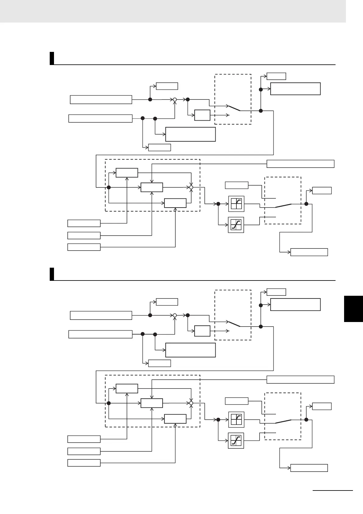
8-1-5 PID2/PID3/PID4 Control
Schematic Diagram of PID2 Control
Schematic Diagram of PID3 Control
+
+
+
+
00
01
[AJ-02]
-
00
01
[AJ-01]
02
[AJ-07]
[AJ-12]
[AJ-13]
×(-1)
[AJ-14]
[AJ-15]
[FA-36]
[db-36]
[db-56]
[db-55]
Proportional gain
PID2 output command
I control integral value clear [PIDC2]
PID2 deviation
excessive [OD2]
PID2 feedback
comparison signal
[FBV2]
PID2 deviation
minus
PID2 target value
PID2 feedback data
Integral gain
Differential gain
P control
PID2 control
I control
D control
0 command
PID2 selection
+
+
+
+
00
01
[AJ-22]
-
00
01
[AJ-21]
02
[AJ-27]
[AJ-32]
[AJ-33]
×(-1)
[AJ-34]
[AJ-35]
[FA-38]
[db-38]
[db-58]
[db-57]
Proportional gain
PID3 output command
I control integral value clear [PIDC3]
PID3 deviation
excessive [OD3]
PID3 feedback
comparison signal
[FBV3]
PID3 deviation
minus
PID3 target value
PID3 feedback data
Integral gain
Differential gain
P control
PID3 control
I control
D control
0 command
PID3 selection

Table of Contents

Related product manuals