EasyManuals Logo

Omron RX2 Series User Manual

Omron RX2 Series
920 pages
To Next Page IconTo Next Page
To Previous Page IconTo Previous Page
Page #426 background imageLoading...
Page #426 background image
8 Applied Settings
8 - 26
High-function General-purpose Inverter RX2 Series User’s Manual
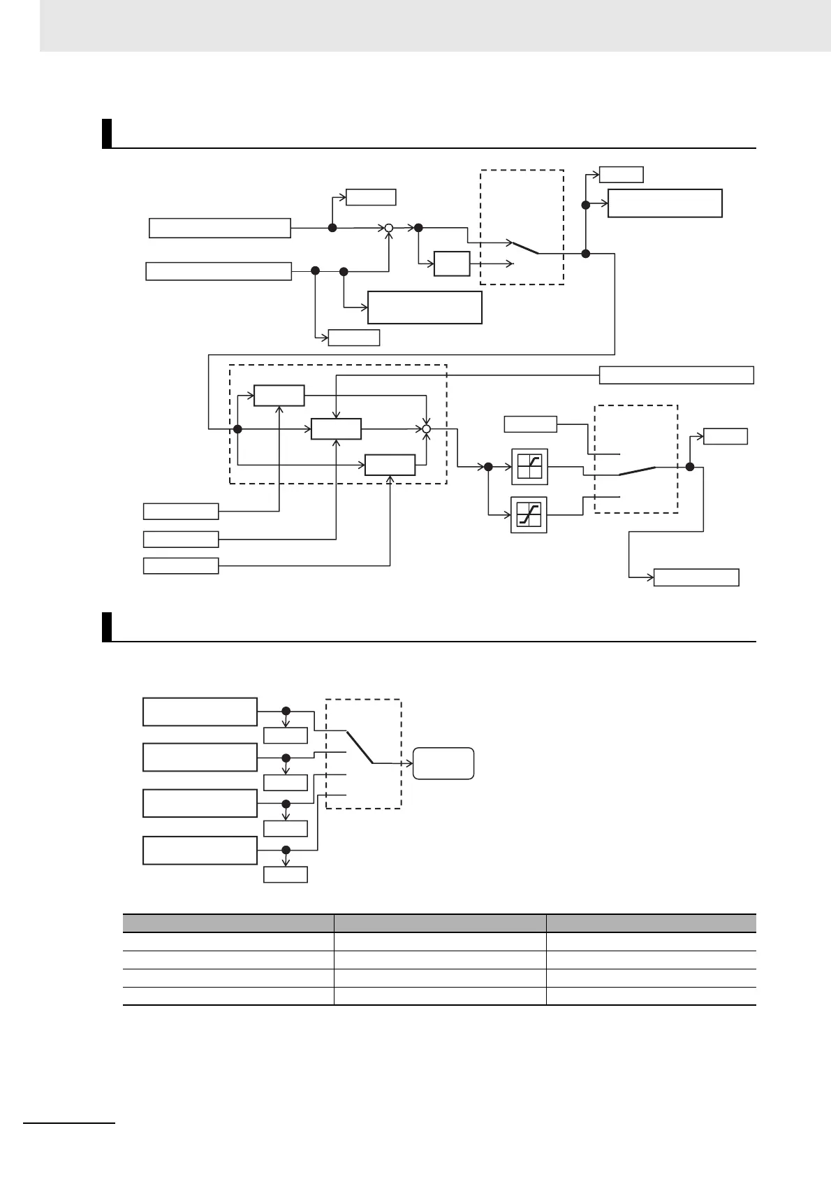
Switching the input terminal function 056[PIO1]/057[PIO2] enables switching and controlling of PID1 to
PID4.
Combination of PIO1/PIO2
Schematic Diagram of PID4 Control
Switching PID1 to PID4
[PIO2] [PIO1]
PID1 is enabled OFF OFF
PID2 is enabled OFF ON
PID3 is enabled ON OFF
PID4 is enabled ON ON
+
+
+
+
00
01
[AJ-42]
-
00
01
[AJ-41]
02
[AJ-47]
[AJ-52]
[AJ-53]
×(-1)
[AJ-54]
[AJ-55]
[FA-40]
[db-40]
[db-60]
[db-59]
Proportional gain
PID2 output command
I control integral value clear [PIDC4]
PID4 deviation
excessive [OD4]
PID4 feedback
Comparison signal
[FBV4]
PID4 deviation
minus
PID4 target value
PID4 feedback data
Integral gain
Differential gain
P control
PID4 control
I control
D control
0 command
PID4 selection
[db-50]
[db-55]
[db-57]
[db-59]
PID1 control
PID output switch
[PIO1]/[PIO2]
PID
Output
command
PID2 control
PID3 control
PID4 control

Table of Contents

Questions and Answers:

Question and Answer IconNeed help?

Do you have a question about the Omron RX2 Series and is the answer not in the manual?

Omron RX2 Series Specifications

General IconGeneral
BrandOmron
ModelRX2 Series
CategoryInverter
LanguageEnglish

Related product manuals