8 - 27
8 Applied Settings
High-function General-purpose Inverter RX2 Series User’s Manual
8-1 PID Control
8
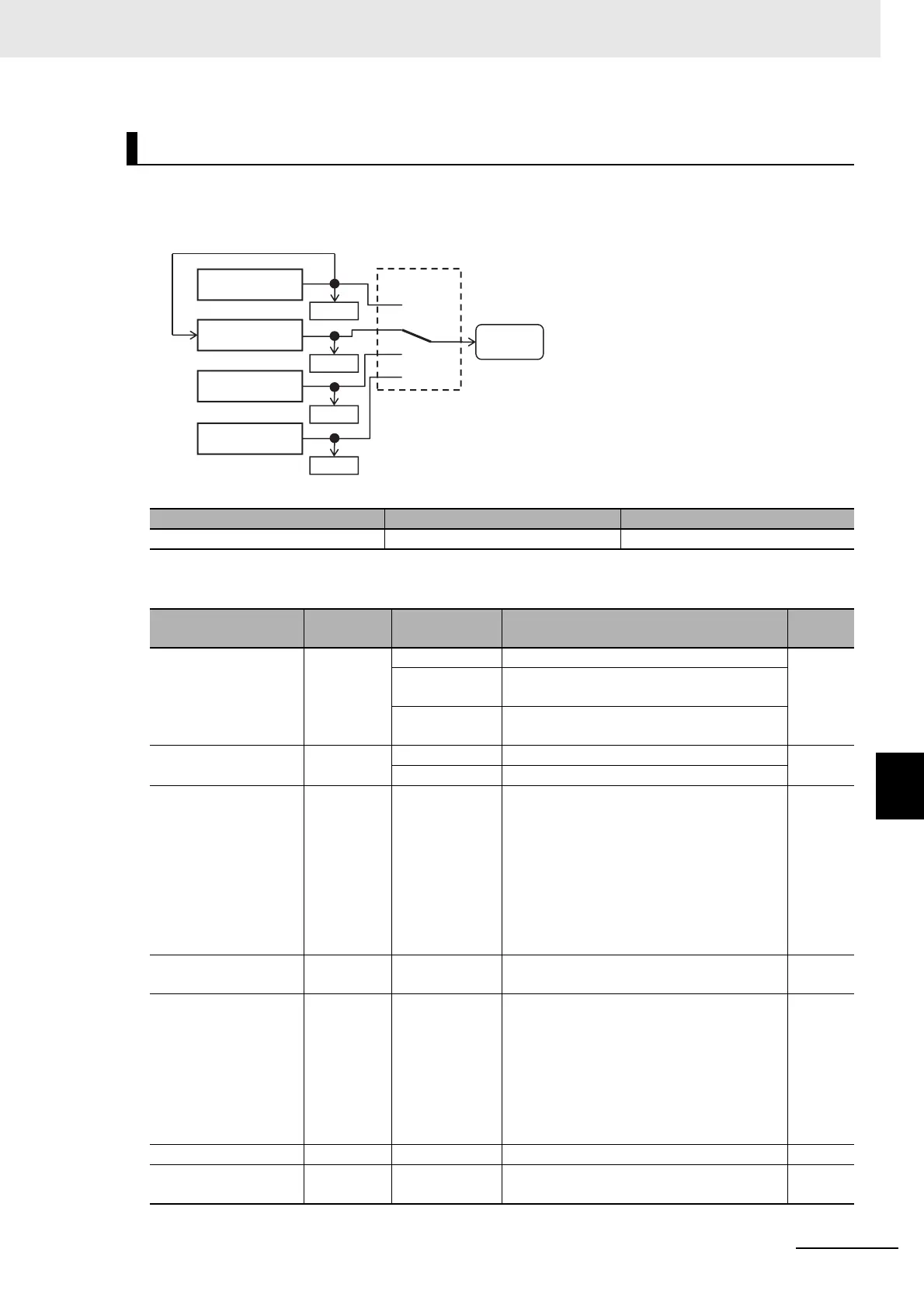
8-1-5 PID2/PID3/PID4 Control
Setting the target value of PID2 to PID1 output ([AJ-07] = 15) enables double-layer control of PID.
(PID3/PID4 cannot be selected.)
Enable PID2 output command as follows.
Combination of PIO1/PIO2
Parameter
Connection of PID1 with PID2
[PIO2] [PIO1]
PID2 is enabled OFF ON
Item Parameter Data Description
Default
data
PID2 enable [AJ-01]
00 Disable
00
01
Enable (if command becomes negative, it
does not output in a reverse direction)
02
Enable (if command becomes negative, it
outputs in a reverse direction)
PID2 deviation inverse [AJ-02]
00 Disable
00
01 Enabled (polarity inversion of deviation)
Input source selection
of Set-point for PID2
[AJ-07] 00 to 15
00: Disable, 01: Ai1-L input, 02: Ai2-L input,
03: Ai3-L input, 04: (Reserved),
05: (Reserved), 06: (Reserved),
07: Parameter setting [AH-44],
08: RS 485 communication, 09: Option 1,
10: Option 2, 11: Option 3,
12: Pulse train input (main unit),
13: Pulse train input (option),
15: PID1 output
07
Set-point setting for
PID2
[AJ-10]
0.00 to
100.00(%)
*1
Is a parameter set value. 0.00
Input source selection
of Process data for
PID2
[AJ-12] 00 to 13
00: Disable, 01: Ai1-L input, 02: Ai2-L input,
03: Ai3-L input, 04: (Reserved),
05: (Reserved), 06: (Reserved),
07: Parameter setting [AH-44],
08: RS 485 communication, 09: P option 1,
10: Option 2, 11: Option 3,
12: Pulse train input (main unit),
13:Pulse train input (option)
02
PID2 proportional gain [AJ-13] 0.0 to 100.0 Proportional gain 0.1
PID2 integral time con-
stant
[AJ-14] 0.0 to 3600.0(s) Integral gain 0.1
[PIO1]/[PIO2]
[db-50]
[db-55]
[db-57]
[db-59]
PID1 control
PID output switch
PID
Output
command
PID2 control
PID3 control
PID4 control