8 Applied Settings
8 - 74
High-function General-purpose Inverter RX2 Series User’s Manual
Use this function to specify whether to output [AL] Alarm signal (error output) (output terminal function
028) when an instantaneous power failure or under-voltage occurs according to [bb-27] Selection of
instantaneous power failure/under-voltage trip during stopping.
Examples 1 to 6 show cases with no retry.
Precautions for Correct Use
• When the power to control power supply terminals R0 and T0 is supplied from main power
supply terminals R, S, and T, and if the control power supply terminals continue to be shut off
for 80 ms or more, it is considered as power failure. After the power supply is recovered, the
inverter performs power-on operation.
• Depending on the load conditions of the motor driven by the inverter, an under-voltage error
[E009], instead of an instantaneous power failure error [E016], may occur.
• The inverter outputs the alarm while the power to control power supply terminals R0 and T0
remains.
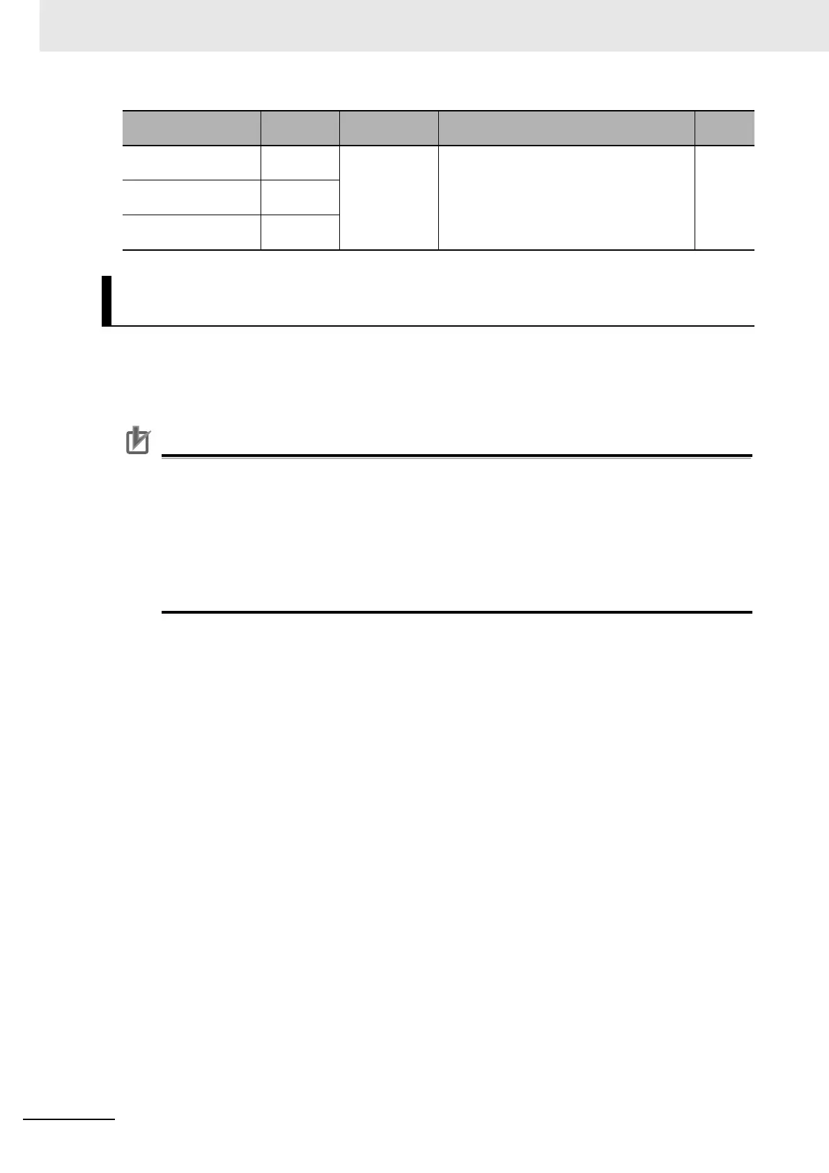
Selection of output ter-
minal function
[CC-01] to
[CC-05]
017
020
021
017: Outputs [AL] Alarm signal.
020: Outputs [IP] Instantaneous power fail-
ure signal
021: Outputs [UV] Under-voltage signal.
-
Relay output terminal
[16] function
[CC-06]
Relay output terminal
[AL] function
[CC-07]
Alarm Output When Instantaneous Power Failure/Under-Voltage
occurs during Stopping
Item Parameter Data Description
Default
data
 Loading...


