8 Applied Settings
8 - 76
High-function General-purpose Inverter RX2 Series User’s Manual
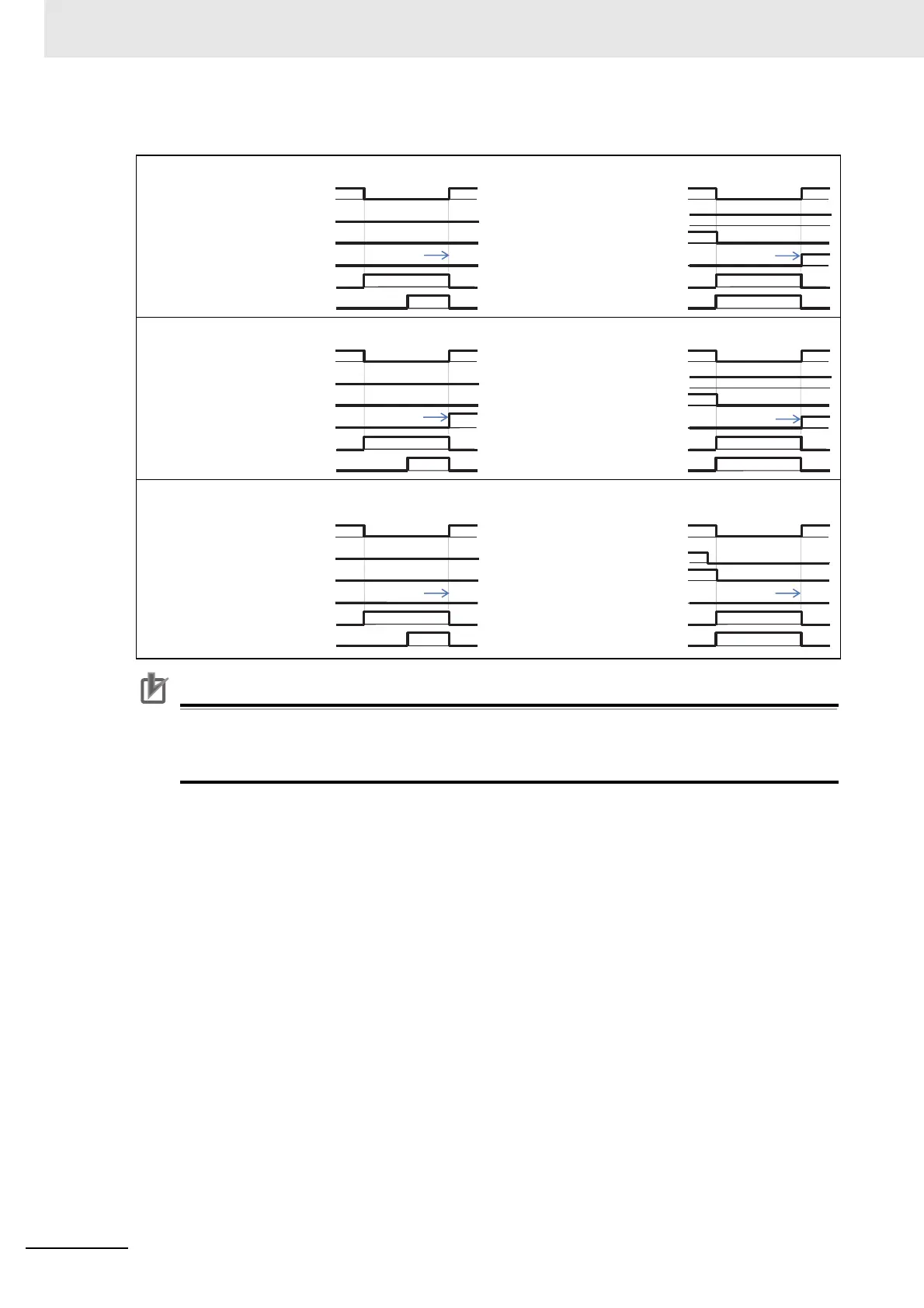
Examples of supplying the power to R0 and T0 from P and N
Precautions for Correct Use
• [IP] signals start to be detected after 3-phase power source has been input to main power
supply terminals R, S, and T.
• If direct current is supplied between P and N, [IP] signals will not be output.
(Ex.4) [bb-27]=00
Power supply
Operation command [FW]
Inverter output
Output terminal [AL]
Output terminal [IP]
Output terminal [UV]
Inverter is stopped
Power supply
Operation command [FW]
Inverter output
Output terminal [AL]
Output terminal [IP]
Output terminal [UV]
Inverter is running
(Ex.5) [bb-27]=01
Power supply
Operation command [FW]
Inverter output
Output terminal [AL]
Output terminal [IP]
Output terminal [UV]
Inverter is stopped
Power supply
Operation command [FW]
Inverter output
Output terminal [AL]
Output terminal [IP]
Output terminal [UV]
Inverter is running
(Ex.6) [bb-27]=02
Power supply
Operation command [FW]
Inverter output
Output terminal [AL]
Output terminal [IP]
Output terminal [UV]
Inverter is stopped
Power supply
Operation command [FW]
Inverter output
Output terminal [AL]
Output terminal [IP]
Output terminal [UV]
Inverter is running (during
deceleration stop)
ON
OFF
OFF
ON
ON
OFF
ON
OFF
ON
OFF
ON
OFF
ON
OFF
OFF
ON
ON
OFF
ON
OFF
ON
OFF
ON
OFF
Power supply
is recovered
ON
OFF
OFF
ON
ON
OFF
ON
OFF
ON
OFF
ON
OFF
Power supply
is recovered
ON
OFF
OFF
ON
ON
OFF
ON
OFF
ON
OFF
ON
OFF
Power supply
is recovered
ON
OFF
OFF
ON
ON
OFF
ON
OFF
ON
OFF
ON
OFF
ON
OFF
OFF
ON
ON
OFF
ON
OFF
ON
OFF
ON
OFF
 Loading...


