8 Applied Settings
8 - 88
High-function General-purpose Inverter RX2 Series User’s Manual
The brake control by managing time is available.
The 037[BRK] brake release signal for the output terminal function and the 037[BOK] brake check sig-
nal for the input terminal function are available.
For the brake control 2, an error occurs with a trip in the following cases.
• When the brake check signal 037[BOK] is used, [BOK] was not turned on within the brake check
waiting time at start-up.
• When the brake check signal 037[BOK] is used, [BOK] was not turned off within the brake check
waiting time at stop.
• When the brake check signal 037[BOK] is used, the brake release signal 037[BRK] was being
output, but [BOK] was turned off.
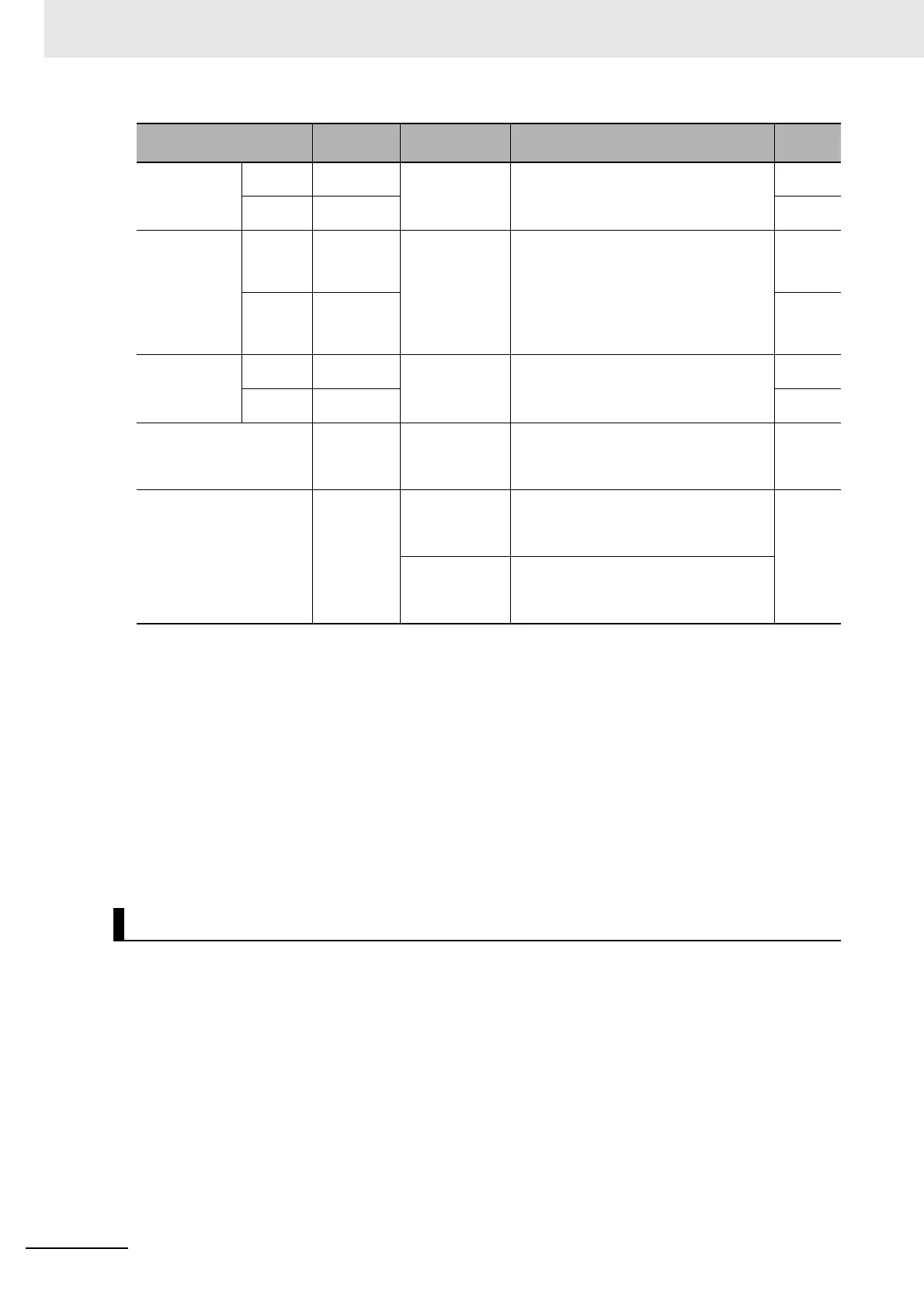
Brake release
frequency
Forward
rotation
[AF135]
0.00 to
590.0(Hz)
Setting the frequency to output the brake
release signal
*2
0.00
Reverse
rotation
[AF142] 0.00
Brake release
current
Forward
rotation
[AF136]
Inverter rated
current
×(0.0 to 2.0)
*3
Setting the output current to allow the
brake release
*4
1.0×
Inverter
rated
current
Reverse
rotation
[AF143]
1.0×
Inverter
rated
current
Brake apply
frequency
Forward
rotation
[AF137]
0.00 to
590.0(Hz)
Setting the frequency to close the brake
at the time of stop
*2
0.00
Reverse
rotation
[AF144] 0.00
Input terminal function
[CA-01] to
[CA-11]
037
[BOK] Brake check signal
OFF: Brake applied
ON: Brake released
-
Output terminal function
[CC-01] to
[CC-07]
037
[BRK] Brake release signal
OFF: Brake application command
ON: Brake release command
-
038
[BER] Brake fault signal
OFF: Brake sequence is normal
ON: Brake sequence is abnormal
*1. If [AF130] = 01, the forward rotation settings, [AF131] to [AF137] are valid for both the forward and reverse
rotations.
*2. Set the time greater than the value of the minimum speed [Hb130].
*3. On the parameter about the current and the voltage, the figures and the units to be handled vary in the setting
path.
1) Operator or CX-Drive: 0.1 A or 0.1 V (When CX-Drive is operated, set [CF-11] Resister data selection to 00
(A,V). When the data of [CF-11] Resister data selection is not set to 00 (A,V), it is not set or displayed correctly.)
2) Modbus: The current and the voltage vary, depending on the setting of Resister data selection [CF-11].
When [CF-11] Resister data selection is set to 00 (A,V), 0.1 A, 0.1 V
When [CF-11] Resister data selection is set to 01 (%), 0.01% (Rated ratio)
3) Drive programming: 0.01% (Rated ratio)
*4. Note that a low value for the setting may generate sufficient torque when releasing the brake.
Brake Control 2
Item Parameter Data Description
Default
data