8 - 89
8 Applied Settings
High-function General-purpose Inverter RX2 Series User’s Manual
8-4 Control Function
8
8-4-4 Brake Control Function (BRK)
[AF130] = 03: Brake control 2, the following parameters are valid.
Precautions for Correct Use
• Since the brake control 2 generates the servo lock status when the brake is on, use 09: zero
speed range sensorless vector control or 10: vector control with sensor for the [AA121] con-
trol method.
• Selecting the control methods other than the above will replace the operation part of the
servo lock with the DC braking operation. Servo lock time is applied at start/stop operation
even when this is a DC injection braking.
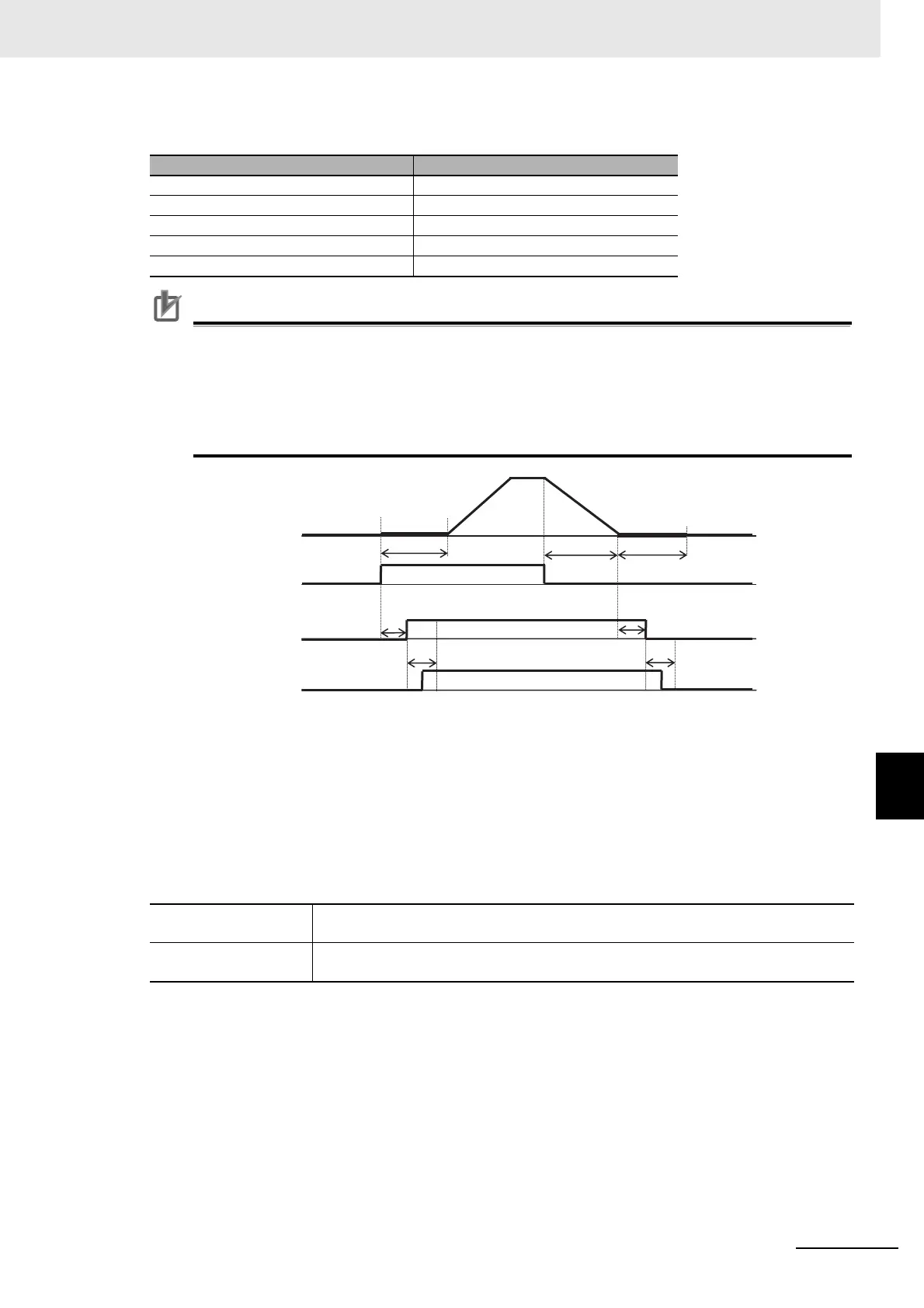
The inverter starts the output and performs the servo lock for the servo lock time at start.
(If the [AA121] control method is neither 09: zero speed range sensorless vector control nor 10: vector
control with sensor, the DC braking is applied.) (1)
After the brake release delay time passes, the brake release signal 037[BRK] is turned on. (2)
The operation varies depending on whether the brake check signal 037[BOK] is set to the input terminal
function.
After the servo lock time at start passes, there is an acceleration. (3)
Item Valid for both forward and reverse
Brake release delay time [AF150]
Brake apply delay time [AF154]
Brake check time [AF152]
Servo lock time at start [AF153]
Servo lock time at stop [AF154]
With [BOK] setting
If the 037[BOK] is not turned on during the brake check time, the inverter trips with the
[E036] brake error outputting the fault signal 038[BER].
Without [BOK] setting
After the release signal 037[BRK] signal is turned on, there is a waiting for the servo
lock time at start to pass.
(1)
(6)
(7)
(4)
(2)
(3)
(5)
Servo lock
time at start
[AF153]
Output
frequency
Operation
command
Brake release signal
037[BRK]
Brake check time [AF152]
Brake release delay time
[AF150]
Brake check signal
037[BOK]
Servo lock
time at stop
[AF154]
Brake check time
[AF152]
Brake apply delay time
[AF151]