8 Applied Settings
8 - 186
High-function General-purpose Inverter RX2 Series User’s Manual
Parameter
When selecting the output monitor, set the registered number of each code. For example, when
using dA-02 of output current monitor via [FM] output terminal, set “10002(2712h)” to [Cd-03].
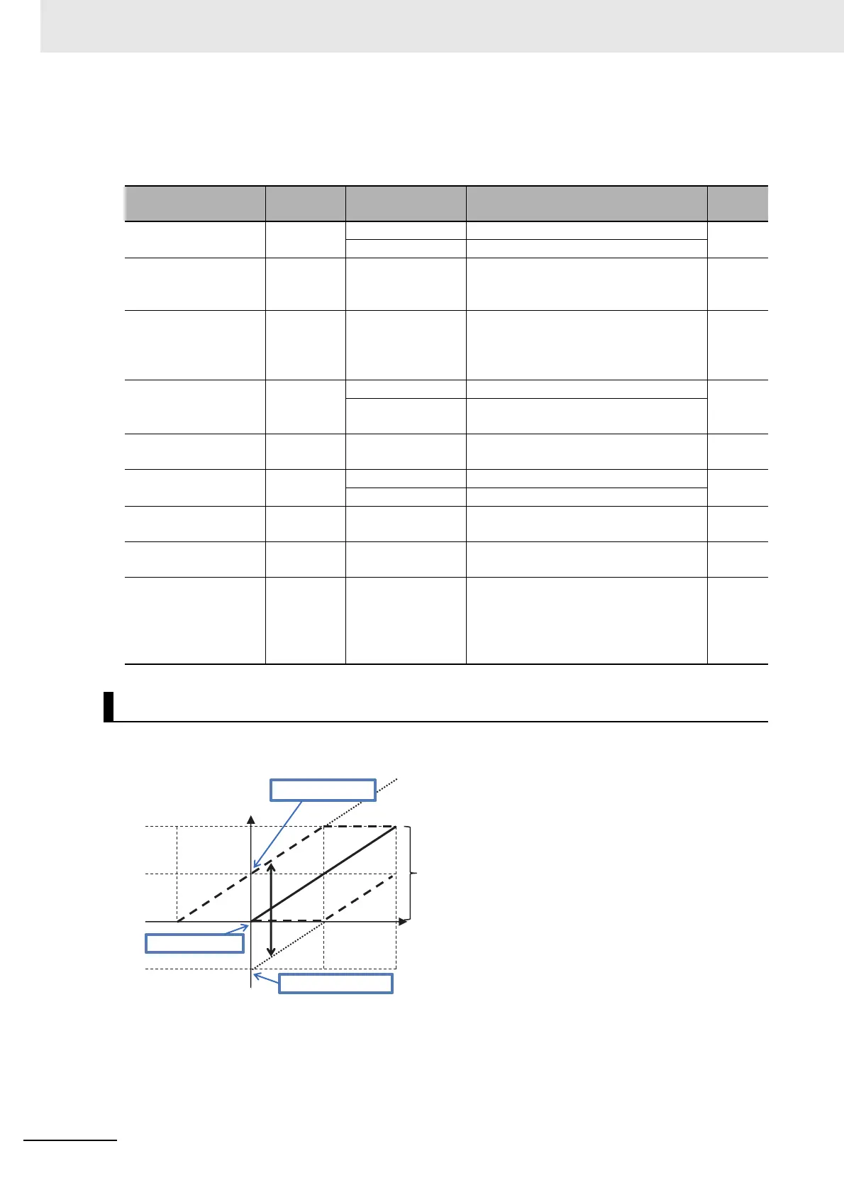
With the “Bias adjustment [Cd-13]” of the “PWM output,” you can bias Point 0 as shown in the below fig-
ure.
Item Parameter Data Description
Default
data
[FM] monitor output
wave form selection
[Cd-01]
00 PWM output (Frequency: 6.4 ms)
00
01 Digital frequency output
[FM] monitor output
base frequency (at
PWM output)
[Cd-02] 0 to 3600[Hz]
[FM] terminal output frequency in the full
scale.
2880
[FM] monitor output
selection
[Cd-03]
Parameter number
for 8-11-4 Analog
Output Terminal
Adjustment on
page 8-178.
Sets a parameter number. [dA-01]
Analog monitor adjust
mode enable
[Cd-10]
00 Invalid.
00
01
Valid. Outputs to terminals output levels
in the adjustment mode.
Filter time constant of
[FM] monitor
[Cd-11] 1 to 500[ms] Filters FM output data. 100
[FM] Data type
selection
[Cd-12]
00 Outputs the absolute value of data.
00
01 Outputs data with a symbol.
[FM] monitor bias
adjustment
[Cd-13] -100.0 to 100.0[%] Biases data to adjust Point 0 of data. 0.0
[FM] monitor gain
adjustment
[Cd-14]
-1000.0 to
1000.0[%]
Apply a gain to data to adjust an inclina-
tion in data.
100.0
Output level setting at
[FM] monitor adjust
mode
[Cd-15] -100.0 to 100.0[%]
Sets output in the adjustment mode. It
selects the maximum output (at 100.0%),
the minimum output (at 0.0%)
([Cd-12]=00), or the minimum output (at
-100.0%) ([Cd-12]=01).
100.0
[Cd-01] [FM] Terminal Output Form Selection is Set to 00
Output scale
Outputting will
be made in this
range.
Maximum
Parallel
movement
 Loading...


