8 - 191
8 Applied Settings
High-function General-purpose Inverter RX2 Series User’s Manual
8-11 Output Terminal Function
8
8-11-6 Output Functions (FM)
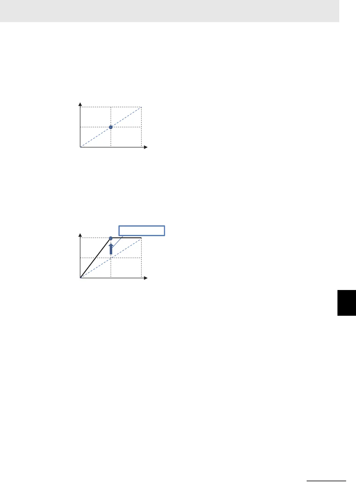
2 When the standard point at which you want to perform outputs is the rated current value, since
the rated current has a maximum scale of Rated current × 2.00, set a point that is half of it. First
set [Cd-12] to 50.0% (corresponding to the inverter rated current).
In this state, since the full scale of the output current monitor is Rated current × 2.00, the [FM]
terminal outputs PWM of 50% duty, which is an output at the rated current (= Rated current ×
2.00 × 50.0%).
3 Adjust the inclination with [Cd-14]. Change [Cd-14] to make an adjustment toward the point from
which PWM of 100% duty is output.
(For example, see and wait with a range from 190.0% to 210.0%.)
[Cd-13]=0.0%, [Cd-14]=200.0%
4 Returning [Cd-10] to 00 starts the PWM output of [FM] that is adjusted.
Rated current × 2 (A)
Output current (A)
Rated current
(A)
Rated current × 2 (A)
Output current (A)
Rated current
(A)