9 - 27
9 Communications Functions
High-function General-purpose Inverter RX2 Series User’s Manual
9-5 Modbus Communication Register Number List
9
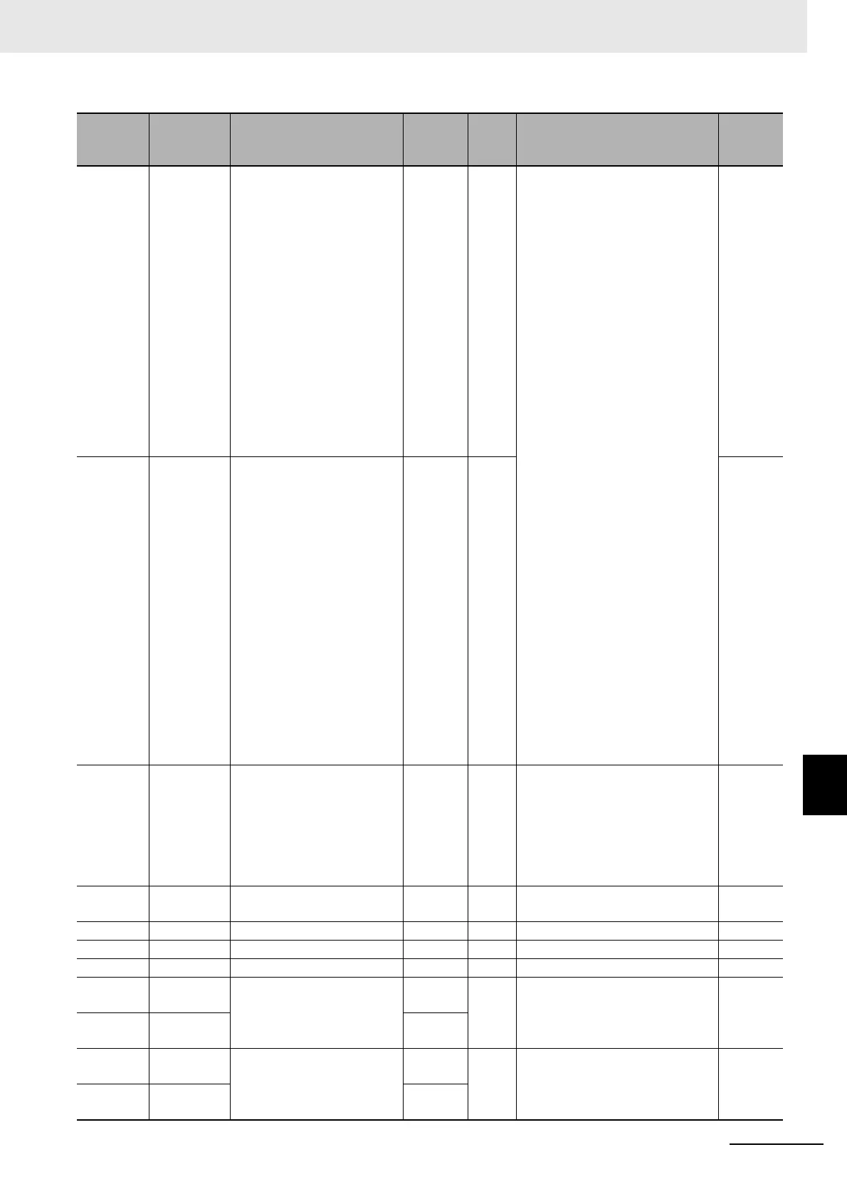
9-5-2 Group d Register List
27DFh 27DEh
Speed command destination
monitor (main)
dC-07 R
00: disabled
01: Ai1
02: Ai2
03: Ai3
04: (Reserved)
05: (Reserved)
06: (Reserved)
07: Multistage speed 0
08: Sub speed
09: Multistage speed 1
10: Multistage speed 2
11: Multistage speed 3
12: Multistage speed 4
13: Multistage speed 5
14: Multistage speed 6
15: Multistage speed 7
16: Multistage speed 8
17: Multistage speed 9
18: Multistage speed 10
19: Multistage speed 11
20: Multistage speed 12
21: Multistage speed 13
22: Multistage speed 14
23: Multistage speed 15
24: JG
25: RS485
26: Option 1
27: Option 2
28: Option 3
29: Pulse array (Inverter)
30: Pulse array (Option)
31: Drive Programming
32: PID
33: (Reserved)
34: AHD retention speed
-
28DFh 27DFh
Speed command destination
monitor (auxiliary)
dC-08 R -
27E2h 27E1h
Operation command desti-
nation monitor
dC-10 R
00: [FW]/[RV] terminal
01: 3 wire
02: RUN key on operator keypad
03: RS485 setting
04: Option 1
05: Option 2
06: Option 3
-
27E7h 27E6h
Cooling fin temperature
monitor
dC-15 R -200 to 2000 0.1(°C)
27E8h 27E7h Life diagnostic monitor dC-16 R 0 to 0xFF 1
27ECh 27EBh Total start-up count dC-20 R 1 to 65535 1
27EDh 27ECh Power-on count dC-21 R 1 to 65535 1
27EEh 27EDh
Cumulative operating hours
monitor during RUN
dC-22
(HIGH)
R 0 to 1000000 1(hr)
27EFh 27EEh
dC-23
(LOW)
27F0h 27EFh
Cumulative power-on time
dC-24
(HIGH)
R 0 to 1000000 1(hr)
27F1h 27F0h
dC-25
(LOW)
Register
No.
Modbus
register
spec. No.
Function name
Parameter
No.
R/W Monitor or setting data
Resolution