2 - 29
2 Design
High-function General-purpose Inverter RX2 Series User’s Manual
2-3 Wiring
2
2-3-3 Arrangement and Function of Control Circuit Terminal Block
For FM output, you can choose the PWM output method at 6.4 ms fixed interval or pulse output method
in which pulse frequency varies. You can control FM output by setting parameters.
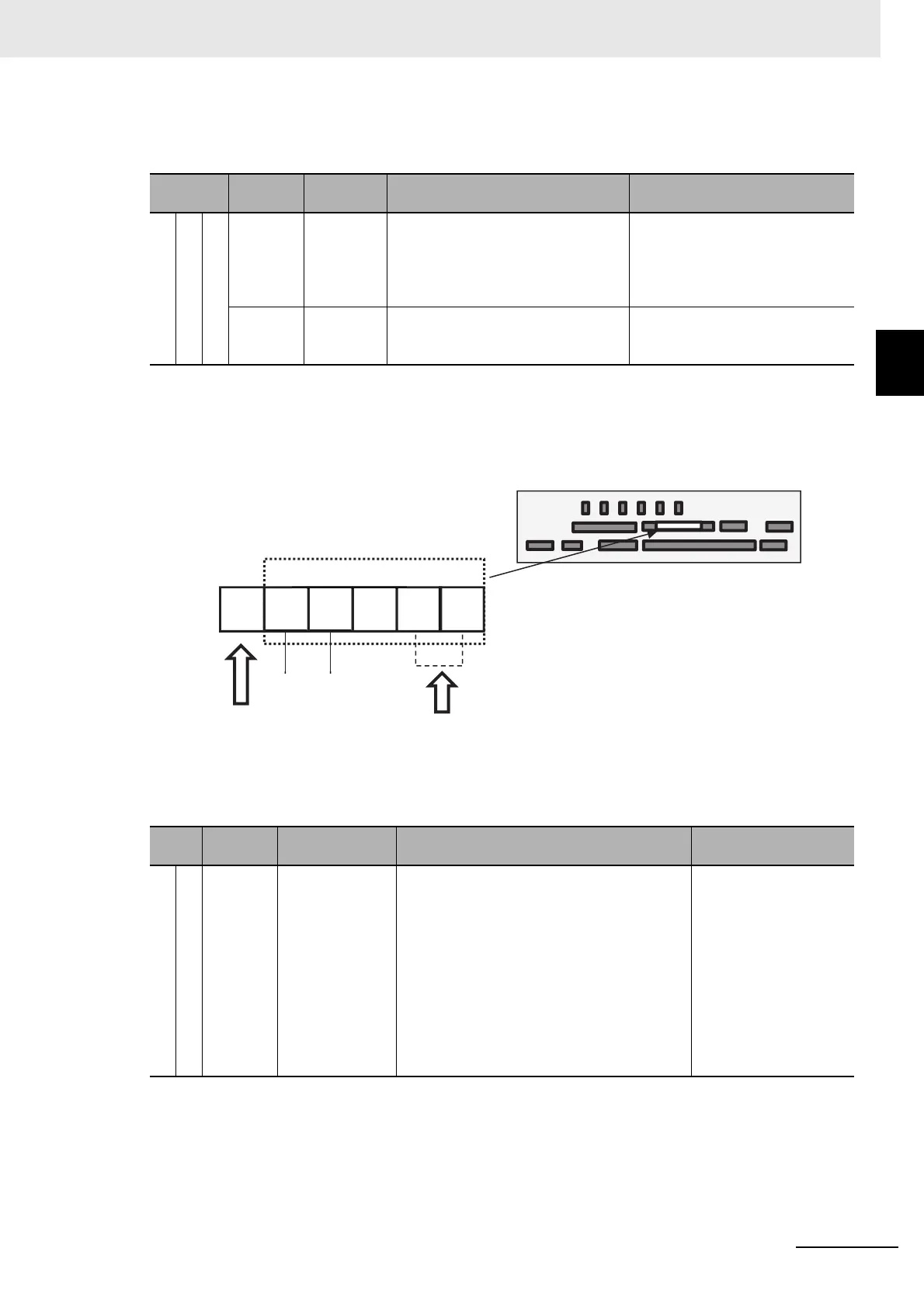
RS485 Communication Terminal Block
Arrangement and configuration of RS485 Communication Terminal Block are described below:
(Wiring example)
SP and SN terminals with the same names are internally connected respectively, so they can be
used for wiring multiple terminals.
Terminal
symbol
Terminal
name
Description Electrical characteristics
Digital
output
Monitor output
FM
Digital
monitor
(voltage)
For digital monitor output, you can
choose the PWM output method at
6.4ms interval or pulse output
method with about 50% duty in which
frequency varies.
Pulse string output DC0-10V
• Maximum allowable current
1.2mA
• Maximum frequency 3.60kHz
CM1
Common
for digital
monitor
The common terminal for digital mon-
itor.
Terminal
symbol
Terminal name Description
Electrical
characteristics
RS485 communication
Serial communication
SP
SN
RP
(CM1)
RS-485 terminal
for Modbus
communication
SP terminal: RS-485 differential (+) signal
SN terminal: RS-485 differential (-) signal
RP terminal: Connect to SP via the terminat-
ing resistor
CM1 terminal: Connect with the signal ground
of an external communication device. (also
used by FM terminal)
There are are two SP terminals and SN termi-
nals each, which are connected internally.
Maximum baud rate is 115.2kbps.
Equipped with terminat-
ing resistor (120Ω)
Enable: Short RP-SN
Disable: Open RP-SN
Control circuit terminal area
Connect CM1 to the SG
(signal ground) of an
external device.
When enabling the terminating
resistor, short RP-SN.
Modbus communication