2 Design
2 - 28
High-function General-purpose Inverter RX2 Series User’s Manual
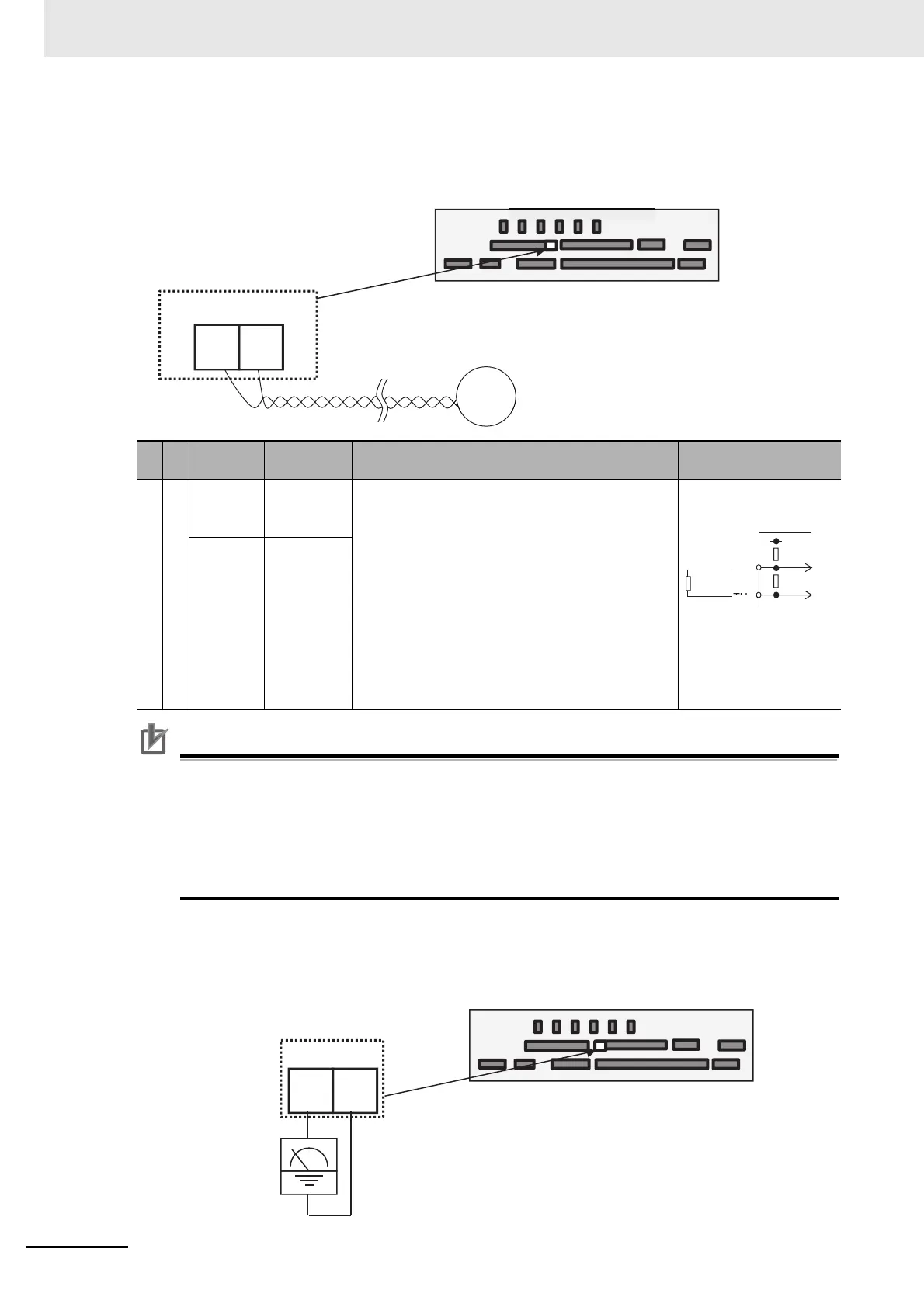
External Thermistor
(Wiring example)
Precautions for Correct Use
To prevent malfunctioning, note the following when performing wiring.
• For connection to the TH terminal, twist only wires connecting to TH+ and TH-, and separate
them from other wires.
• Since the current flowing in the thermistor is very weak, separate the wires from main circuit
line (power line).
• The length of wiring to the thermistor shall be within 20m.
FM Output Terminal
(Wiring example)
Terminal
symbol
Terminal
name
Description
Electrical
characteristics
Thermistor terminal
Analog input
TH+
External
thermistor
input
When an external thermistor is connected, and
resistance abnormality occurs due to abnormal
temperature, etc., trip the inverter.
Connect the thermistor with TH+ and TH-. The
level of detecting resistance abnormality can be
adjusted from 0 to 10000Ω.
[Recommended thermistor characteristics]
Recommended product: SHIBAURA ELECTRON-
ICS Co., Ltd. PB-41E
Allowable rated power: 100mW or more
Impedance at abnormal temperature: 3kΩ
0 to 5 VDC
[Input circuit]
TH-
Common
for external
thermistor
TH-TH+
Control circuit terminal area
External thermistor
terminal
Thermistor
FM CM1
Digital output
Control circuit terminal area