2 - 27
2 Design
High-function General-purpose Inverter RX2 Series User’s Manual
2-3 Wiring
2
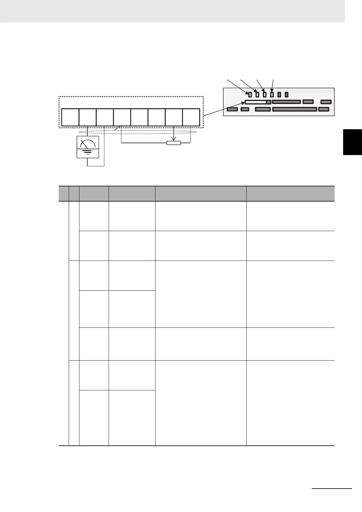
2-3-3 Arrangement and Function of Control Circuit Terminal Block
Analog Input/Output
(Wiring example)
Terminal
symbol
Terminal name Description Electrical characteristics
Analog input terminal for switching voltage and current
Power supply
L
Analog power
common
Common terminals for analog input
terminals (Ai1, Ai2, Ai3) and analog
output terminals (Ao1, Ao2). There
are two L terminals.
H
Power supply for
setting speed
This is a 10V VDC power supply. It
is used when using analog input
terminals (Ai1, Ai2, Ai3) and vari-
able resistor for inputting voltage.
Maximum allowable input current
20mA
Analog input
Ai1
Analog
input terminal 1
(voltage/current
switching SW1)
For Ai1 and Ai2, 0-10 VDC voltage
input and 0-20 mA current input can
be switched using a switch for use.
It can be used for input frequency
command or feedback.
In the case of voltage input:
• Input impedance about 10kΩ
• Allowable input voltage -0.3 to
12V
In the case of current input:
• Input impedance about 100Ω
• Maximum allowable input cur-
rent 24 mA
Ai2
Analog
input terminal 2
(voltage/current
switching SW2)
Ai3
Analog
input terminal 3
-10 to 10 VDC voltage input is avail-
able. It can be used for input fre-
quency command or feedback.
Only voltage input:
• Input impedance about 10 kΩ
• Allowable voltage input -12 to
12 VDC
Analog output
Ao1
Analog
output terminal 1
(voltage/current
switching SW3)
For Ao1 and Ao2, 0-10 VDC volt-
age output and 0-20 mA current
output can be switched using a
switch as output of information
monitor data of the inverter.
In the case of voltage output:
• Maximum allowable output cur-
rent 2 mA
• Output voltage accuracy ±10%
(Ambient temperature: 25±10°C)
In the case of current input:
• Allowable load impedance 250Ω
or below
• Output current accuracy: ±20%
(Ambient temperature: 25±10°C)
Ao2
Analog
output terminal 2
(voltage/current
switching SW4)
Ao2 Ao1 HAi1Ai2Ai3LL
SW4 SW3 SW2 SW1
Analog input/output
Frequency
meter
Variable resistor for frequency command
(0.5-2kΩ)
* A resistor of 1kΩ and 1W or above is
recommended.
• In the example shown on the left, voltage is
input when the variable resistor is used in
H-Ai1-L, therefore, set the SW1 of analog
input 1 (Ai1) to the voltage side.
• In the example shown on the left, if the fre-
quency meter supports current measurement
feature (4-20mA), set the SW3 of analog out-
put 1 (Ao1) to the current side.
Control circuit
terminal area