2 Design
2 - 26
High-function General-purpose Inverter RX2 Series User’s Manual
Precautions for Correct Use
• [AL] function is assigned to [CC-07] C contact relay of AL1-AL0/AL2-AL0 as initial state. Set
the alarm signal of output terminal 017 [AL] function to any of [CC-01] to [CC-07] and outputs
the signal.
The behavior of alarm relay AL1-AL0/AL2-AL0 is shown in the below table.
Precautions for Correct Use
• Factory default settings are shown below. You can change the setting for your needs.
Analog input terminal setting switch: Ai1 (SW1) = Voltage input, Ai2 (SW2) = Current input
Analog output terminal setting switch: Ao1 (SW3) = Voltage output, Ao2 (SW4) = Current
output
• When shipped from the factory, wiring is performed so that STO input is disabled.
• Do not short between the analog power supply H and L terminals, power supply P+ and P-
terminals, P24 and P- terminals, P+ and CM1 terminals, and P24 and CM1 terminals. Other-
wise, the inverter may fail.
[CC-17]
Control
power supply
Inverter error output
Output terminal states
AL1-AL0 AL2-AL0
00
ON
Normal Open Close
Alarm output Close Open
OFF - Open Close
01
ON
Normal Close Open
Alarm output Open Close
OFF - Open Close
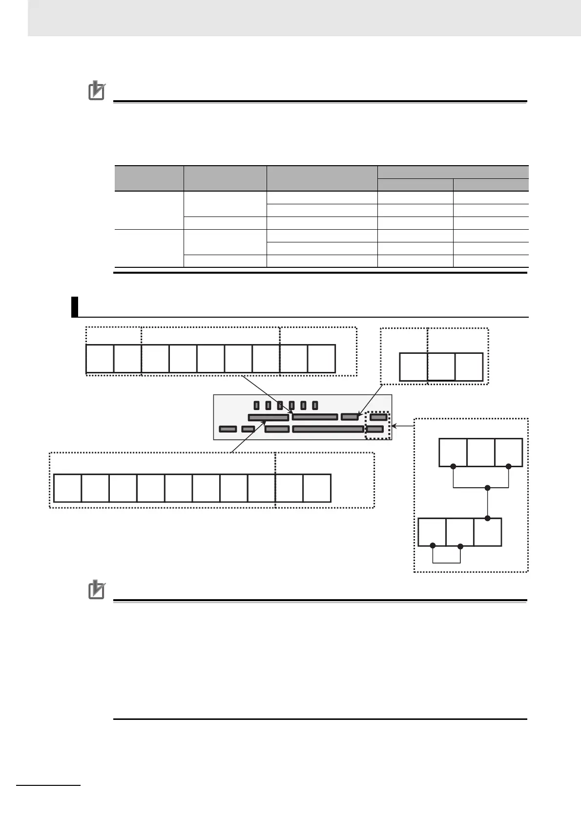
Wiring Portion Above Control Circuit
P+P24 P-
FM RPSNSPSNSPCM1 ED-ED+
Ao2 Ao1 HAi1Ai2Ai3LL TH-TH+
P24S STC CMS
ST1ST2 STC
Digital output Modbus communication EDM output
Control circuit terminal area
External 24V
terminal
Power supply
24V terminal
STO input
External thermistor
terminal
Analog input/output