2 - 25
2 Design
High-function General-purpose Inverter RX2 Series User’s Manual
2-3 Wiring
2
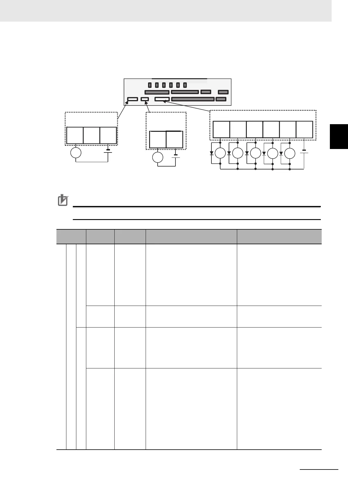
2-3-3 Arrangement and Function of Control Circuit Terminal Block
Output Terminals
(Wiring example)
[ ] indicates the factory default setting.
Precautions for Correct Use
Make sure to use diode. Otherwise the internal circuit may be damaged.
Terminal
symbol
Terminal
name
Description Electrical characteristics
Output terminal
Digital output
Open collector
15,14
13,12
11
Output
terminal
You can select terminal functions
using the parameter settings corre-
sponding to each terminal.
These terminals can be used both in
sink logic or source logic.
Open collector output
• Between each terminal and
CM2
• Voltage drop at ON: 4V or below
• Maximum allowable voltage:
27V
• Maximum allowable current:
50mA
CM2
Common
for output
terminal
Common terminals for output termi-
nals 11-15
Relay
16A
16C
1a relay
terminal
A relay for contact A output.
Maximum capacity of contact
• AC250V, 2A (resistance)/
AC250V, 1A (induction)
Minimum capacity of contact
•DC1V,1mA
AL0
AL1
AL2
1c relay
terminal
A relay for contact C output.
Maximum capacity of contact
AL1/AL0:
• AC250V, 2A (resistance)/
AC250V, 0.2A (induction)
AL2/AL0:
• AC250V, 1A (resistance)/
• AC250V, 0.2A (induction)
Minimum capacity of contact
(common)
• AC100V, 10mA/DC5V, 100mA
AL:[AL] 16:[ZS]
○
X
:
○
RY
:
11
[RUN]
12
[FA1]
13
[FA2]
14
[IRDY]
15
[OL]
CM2
RY RY RY
RY RY
16A 16C
X
AL2 AL1 AL0
X
Devices such as lamp, relay, PLC
Relay
Alarm relay output
terminal
Relay output
terminal
Output terminals
Control circuit terminal area