Appendices C Table of Parameters
C - 18
High-function General-purpose Inverter RX2 Series User’s Manual
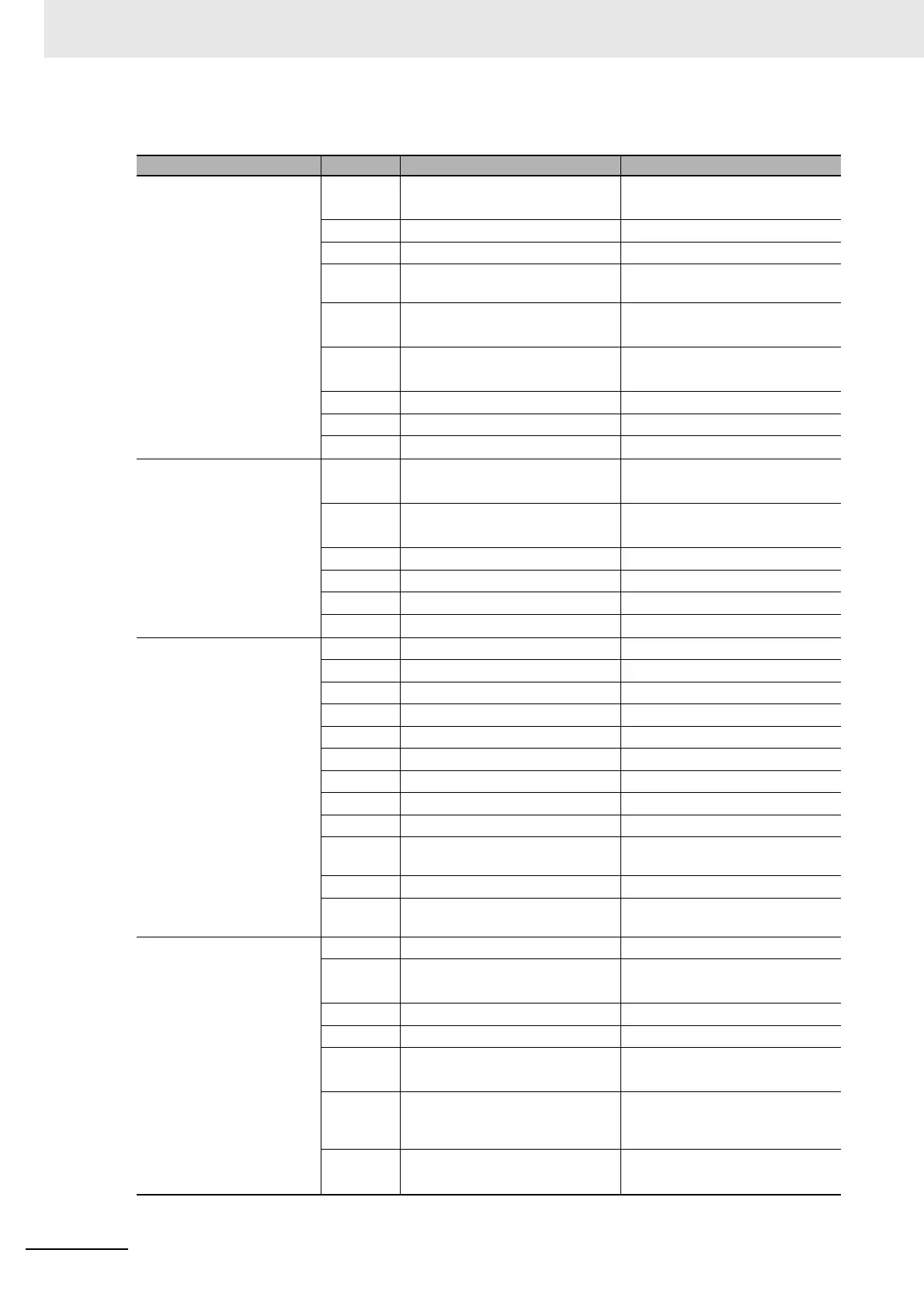
Details of Trip Retry
Function name code mode LCD operator
Inverter state
0
During power supply turned ON,
reset, customer-initializing
INIT.
1 Ground fault detecting GND fault
2 During stop Stop
3
Operation standby (contactor
applied)
Run PREP.1
4
Operation ready (magnetic posi-
tion detecting)
Run PREP.2
5
During RUN (including DB, Servo
ON, forcing)
Run
6 Stop Standby (contactor open) Stop PREP.
7 Retry waiting Retry PREP.
8 During retry Retry
LAD state
0
Zero (output shut off, DB, Servo
On, forcing)
-
1
At startup, forward/reverse
switching,voltage reducing start
MIN.
2 During acceleration ACCEL.
3 During deceleration DECEL.
4 During constant speed CONST.
5 During restart Restart
INV control mode
0 Power shut off -
1 During speed control SPD CNTL
2 During startup Starting
3 During DB DB
4 During forcing Forcing
5 During Servo ON Servo ON
6 During position control POS CNTL
7 During torque control TRQ CNTL
8 During restart Restarting
9
During detection of magnetic pole
position
Axis POS
10 During ground fault detection GND fault
11
During measurement of auto-tun-
ing R1R2L
Tuning
Limit state
0 Not limited status -
1
During overcurrent suppression
(priority order of display is high)
OC SUPPR
2 During overload suppression OL SUPPR
3 During overvoltage suppression OV SUPPR
4
During torque limit (priority order
of display is low)
TRQ Limit
5
During setting limitation of upper
and lower limit and jump fre-
quency
Freq Limit
6
During setting limitation of mini-
mum frequency
Min.Freq