C - 37
Appendices C Table of Parameters
High-function General-purpose Inverter RX2 Series User’s Manual
C-3 Parameter List
C
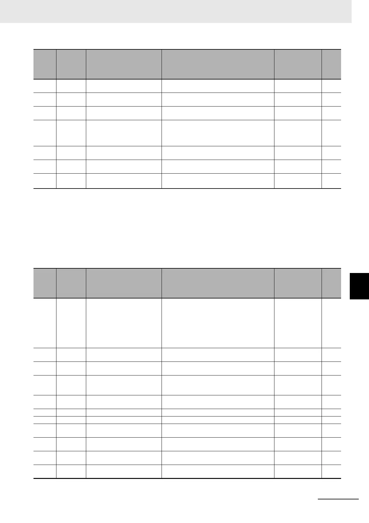
bA242 ○
Over-voltage suppression
action time, 2nd-motor
0.00 to 3600.00 (s) 1.00
bA244 ○
DC bus constant control propor-
tional gain, 2nd-motor
0.00 to 5.00 0.20
bA245 ○
DC bus constant control integral
gain, 2nd-motor
0.00 to 150.00 (s) 1.00
bA246 ○
Over magnetization function
selection, 2nd-motor
00 (Disabled)/01 (Regular operation)/
02 (Operation only at deceleration)/
03 (Level mode)/
04 (Level mode only at deceleration)
02
bA247 ○
Over magnetization output filter
time constant, 2nd-motor
0.00 to 1.00 (s) 0.30
bA248 ○
Over magnetization voltage
gain, 2nd-motor
50 to 400 (%) 100
bA249 ○
Over magnetization level set-
ting, 2nd-motor
(200 V class) 330.0 to 400.0 (V)
(400 V class) 660.0 to 800.0 (V)
(200 V class) 360.0
(400 V class) 720.0
*1. On the parameter about the current and the voltage, the figures and the units to be handled vary in the setting path.
1) Operator or CX-Drive: 0.1 A or 0.1 V (When CX-Drive is operated, set [CF-11] Resister data selection to 00 (A,V). When the data of
[CF-11] Resister data selection is not set to 00 (A,V), it is not set or displayed correctly.)
2) Modbus: The current and the voltage vary, depending on the setting of Resister data selection [CF-11].
When [CF-11] Resister data selection is set to 00 (A,V), 0.1 A, 0.1 V
When [CF-11] Resister data selection is set to 01 (%), 0.01% (Rated ratio)
3) Drive programming: 0.01% (Rated ratio)
*2. 1.8 × Inverter rated current (A)
*3. 1.5 × Inverter rated current (A)
*4. Minimum resistance values vary in inverter model.
Code
Codes that
can be
changed
during
operation
Name Data range Initial value Note
bb101 ○ Carrier speed setting, 1st-motor
[Ub-03]=02: Normal duty
0.5 to 16.0 (kHz)
[Ub-03]=01: Low duty
0.5 to 12.0 (kHz)
[Ub-03]=00: Very low duty
0.5 to 10.0 (kHz)
*1
2.0
bb102 -
Sprinkle carrier pattern selec-
tion, 1st-motor
00 (Disabled)/01 (Pattern 1 enabled)/
02 (Pattern 2 enabled)/03 (Pattern 3 enabled)/
00
bb103 ○
Automatic-carrier reduction
selection, 1st-motor
00 (Disabled)/01 (Enabled: current)/
02 (Enabled: temperature)
00
bb-10 - Automatic error reset selection
00 (Disabled)/
01 (Enabled with operation command OFF)/
02 (Enable after the setting time)
00
bb-11 -
Alarm signal selection at Auto-
matic error reset is active
00 (Output)/01 (Not output) 00
bb-12 - Automatic error reset wait time 0 to 600 (s) 2
bb-13 - Automatic error reset number 0 to 10 3
bb-20 -
The number of retries after
instantaneous power failure
0 to 16/255 0
bb-21 -
The number of retries after
under voltage
0 to 16/255 0
bb-22 -
The number of retries after over
current
0 to 5 0
bb-23 -
The number of retries after over
voltage
0 to 5 0
Code
Codes that
can be
changed
during
operation
Name Data range Initial value Note

 Loading...


