Appliance Cluster Configuration
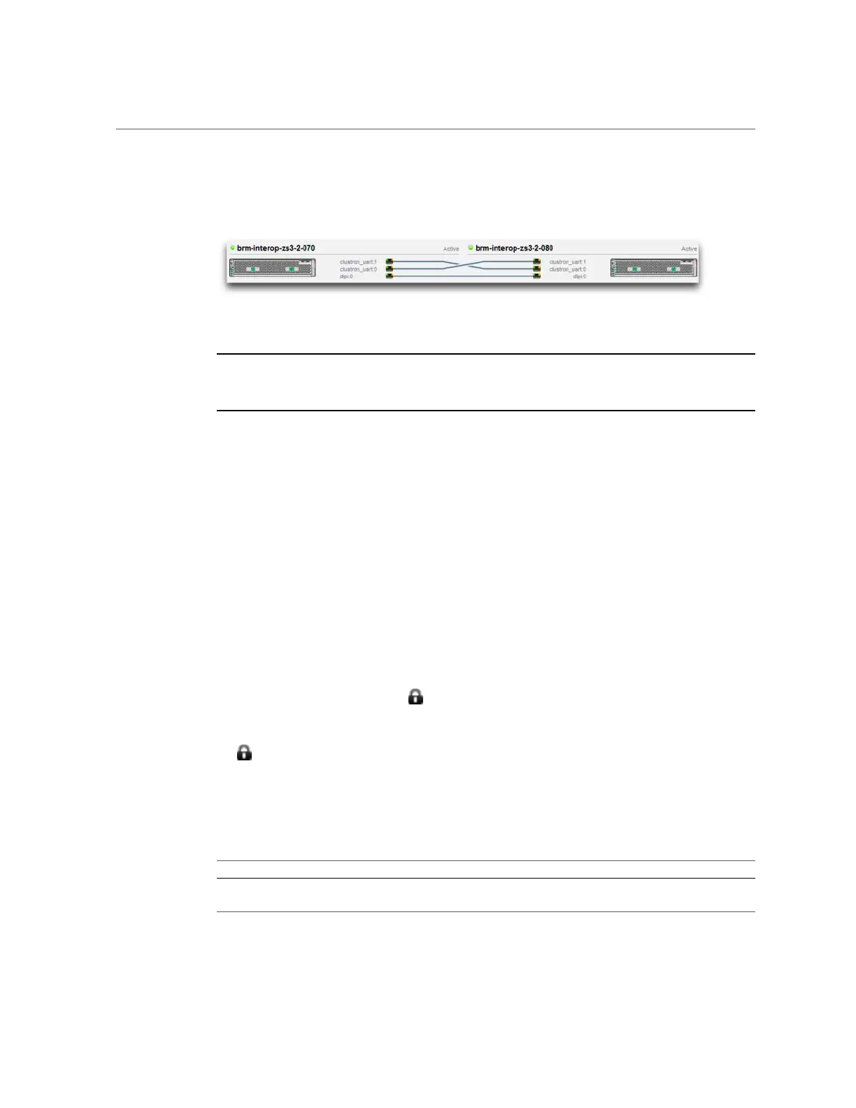
FIGURE 14
Cluster Connections
Note - Cluster cables must be connected between the two controllers to see the three solid line
connections in the BUI. For cluster cabling details, see “Connecting Cluster Cables” in Oracle
ZFS Storage Appliance Cabling Guide.
The interface contains the following objects:
■
A thumbnail picture of each system, with the system whose administrative interface is being
accessed shown at left. Each thumbnail is labeled with the canonical appliance name, and its
current cluster state (the icon above, and a descriptive label).
■
A thumbnail of each cluster card connection that dynamically updates with the hardware: a
solid line connects a link when that link is connected and active, and the line disappears if
that connection is broken or while the other system is restarting/rebooting.
■
A list of the PRIVATE and SINGLETON resources currently assigned to each system,
shown in lists below the thumbnail of each cluster node, along with various attributes of the
resources.
■
For each resource, the appliance to which that resource is assigned (that is, the appliance
that will provide the resource when both are in the CLUSTERED state). When the current
appliance is in the OWNER state, the owner field is shown as a pop-up menu that can be
edited and then committed by clicking Apply.
■
For each resource, a lock icon indicating whether or not the resource is PRIVATE. When
the current appliance is in either of the OWNER or CLUSTERED states, a resource can be
locked to it (made PRIVATE) or unlocked (made a SINGLETON) by clicking the lock icon
and then clicking Apply. Note that PRIVATE resources belonging to the remote peer will
not be displayed on either resource list.
The BUI contains the following buttons:
TABLE 42
Cluster Interface Buttons
Button Description
Setup If the cluster is not yet configured, execute the cluster
setup guided task, and then return to the current screen.
194 Oracle ZFS Storage Appliance Administration Guide, Release OS8.6.x • September 2016

 Loading...


