DOB 1300-1556 | X3-45 Commuter PA-1648 Maintenance Manual First release Oct 2020
53
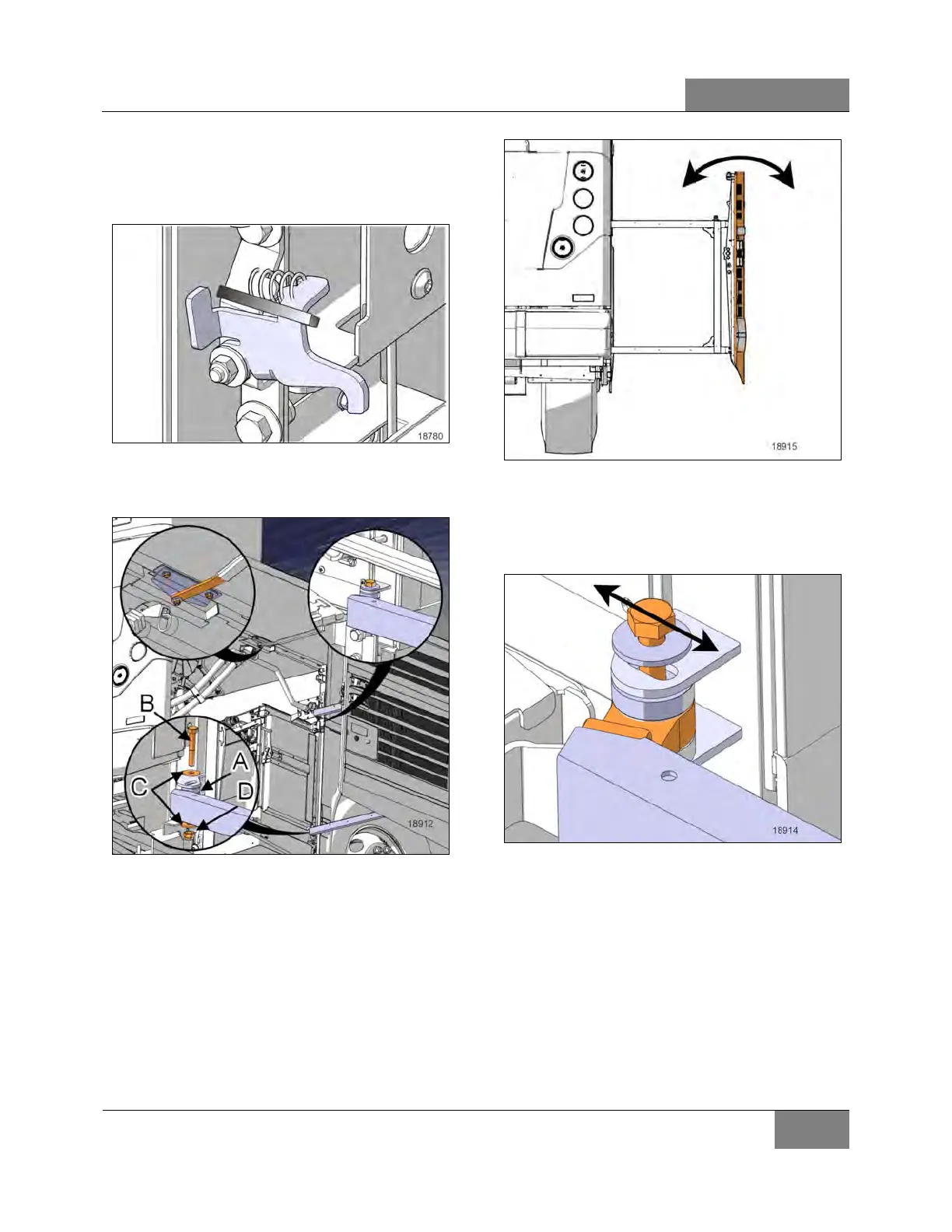
6. Temporarily secure the secondary lock in the
depressed position with a cable tie so it does
not interfere with adjustments. Remove
cable tie once completed.
FIGURE 91: SECONDARY LOCK
7. Locate important components on the
mechanism.
FIGURE 92: DOOR INSTALLATION
A) SPACERS
B) SCREWS
C) FLAT WASHERS
D) NUTS
8. Close the door gently.
9. Adjust the vertical angle of the door.
FIGURE 93: DOOR VERTICAL ANGLE
10. Use the adjustment screw between the
upper arm and the structure to adjust the
vertical angle of the door until it sits properly
on the four rubber stoppers.
FIGURE 94: UPPER ARM ADJUSTMENT SCREW
11. Adjust the both rubber stoppers to make all
the surfaces marked with an ‘’X’’ in Figure
95 flush with the door surface within a
tolerance of ±1mm.
 Loading...


