68
DOB 1300-1556 | X3-45 Commuter PA-1648 Maintenance Manual First release Oct 2020
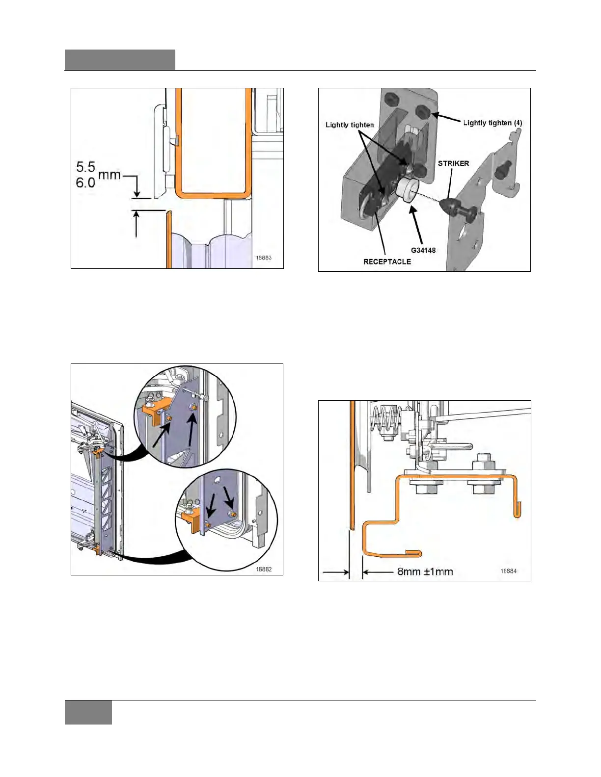
FIGURE 128: ''Z'' DIRECTION ADJUSTMENT
18. For the ‘’Y’’ direction, on the hinge side,
loosen the screws shown in Figure 129 to
allows adjustment.
19. Adjust the door exterior panel side flush with
the compartment door and the fender.
FIGURE 129: ''Y'' DIRECTION ADJUSTMENT SCREWS
20. Tighten the hinge screws.
21. On the striker side, the locking device is
used to adjust the ‘’Y’’ direction.
22. To allow adjustment of the latch mechanism,
lightly tighten the retaining hardware on
receptacle and receptacle support to frame.
FIGURE 130: STRIKER SIDE ADJUSTMENT
23. Place centering tool G34148_500 in the
receptacle cavity.
24. Close door to center the latch assembly.
25. Tighten the Receptacle screws only.
26. Door exterior panel on latch side should be
positioned at 8mm ±1mm from frame as
shown in Figure 131. Make the adjustments
by moving the receptacle support.
FIGURE 131: STRIKER SIDE TOP VIEW
 Loading...


