DOB 1300-1556| X3-45 Commuter PA-1648 Maintenance Manual Section 23 revised Nov 2021
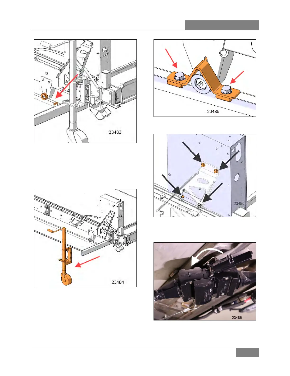
FIGURE 16: SLIDE THE CASSETTE INSIDE THE
COMPARTMENT
Drop down the front side of the cassette until it
gets contact with the rail and make sure the
rollers are aligned with the V-rail.
Remove the jacks (2) on the front side of the
cassette.
FIGURE 17: JACKS REMOVAL
Install the fasteners on the dismounted jacks.
Install locks in four locations and tighten screws:
TORQUE:.55-65 lb-ft (75-88 Nm)
FIGURE 18: ANCHOR BOLTS INSTALLATION
Reinstall the control box with 4 screws.
FIGURE 19: CONTROL BOX DISMOUNTING
Plug the electrical connectors and lock it with the
connector cover.
FIGURE 20: ELECTRICAL CONNECTION
 Loading...


