ENGINE REPAIR 6A-73
Removal and repair of gear box and oil pump
NOTE:
Clean thoroughly removed components , left overs from
gaskets and sealant.
CAUTION:
Clean using pressurized air oil flow conductions,
linkages, filter support, heat exchanger support and
the heat exchanger itself.
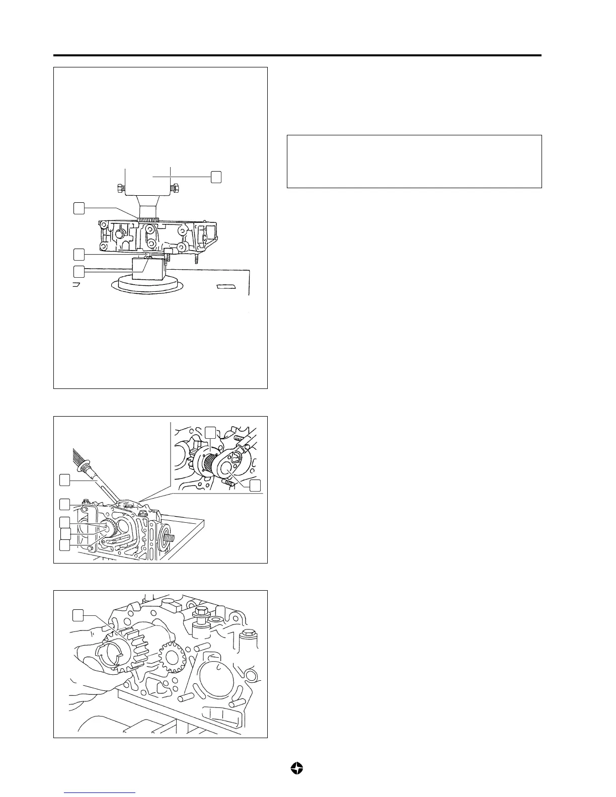
Installation of gears
1) Install gear (25) and axle (26) of oil pump, using a hydraulic
press (D).
For this task, heat gear (25) and cool axle (26), the difference
of temperatures between both pieces being some ~270° C.
Once done, control height between upper plane of gear (25)
and external plane of gear (27) (end of axle (26)).
Height between external plane of gear (25) and (27):
88 - 0,2 mm
2) Check torque of resistance to rotation between gear (25)
and axle (26) of oil pump, as follows:
• Fit tool (E) ref. 790974 to avoid turnings at the gear (25).
• Draw two reference signals (F) aligned on gear (25) and on
axle (26).
• Apply specified tightening torque on axle (26), using
dynamometric key (G) and tool (H) ref. 790974.
• Ensure that signals (F) keep perfectly aligned after applying
the specified torque.
Torque of resistance between gear (25) and axle (26):
6,4 Kg-m (64 Nm)
3) Install axle and driven gear (22) of oil pump.
25
26
27
D
G
H
G
E
F
26
25
22

 Loading...