ENGINE FUEL AND EMISSION CONTROL SYSTEM 6C-25
GENERAL DESCRIPTION
A piston pump supplies the fuel at a regular pressure
equivalent to that of the injection (up to 1350 bar).
A two-way electro-valve takes from the pump supply, the
appropriate amount of fuel to regulate the desired pressure
value.
The pressurised fuel accumulates in a collector (rail) which
contains the pressure oscillations (ripple).
The electro-injectors are fed by the rail and their working is
determined by the stimulation of a rapid electromagnetic
operator (integrated in the body of each electro-injector)
opening an aperture which causes a pressure difference.
This difference allows the opening of the injector end
producing the spray.
An electronic control unit, in which the control and power
units for the electro-injector piloting are integrated, is
prepared for the control of the entire injection system.
Some sensors, connected to the control board, can deter-
mine the state of the engine and the injection system at
every moment as well as the demand for power by the
driver.
Moreover, the system can control an operator for the EGR
and for the turbocompressor with waste-gate, or a variable
geometry turbocompressor.
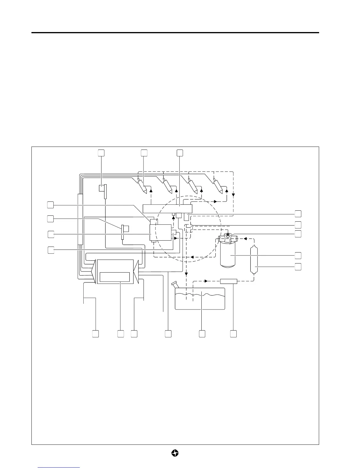
HIGH PRESSURE ELECTRONIC INJECTION SYSTEM FUNCTIONAL DIAGRAM
1.- 3
rd
pinston deastintor valve
2.- Crankshaft position sensor
3.- High pressure pump
4.- Pressure regulator
5.- Other actuators (thermostarter, fuel heater, electro-fan control, air-
conditioning compressor control)
6.- Electronic control unit with atmospheric pressure sensor
7.- Other sensors (accelerator, brake, clutch, vehicle speed, water
temperature, admission air temperature)
8.- Hydraulic accumulator (Rail) pressure sensor
9.- Fuel tank
10.- Prefilter
11.- Fuel supply electro-pump
12.-Fuel filter
13.-Filter over-pressure valve
14.- Multiple connector for excess fuel (5-way)
1
2
3
4
5 6 7
8 9 10
11
12
13
14
15
161718
15.-Hydraulic accumulator (rail) pressure limiter
16.-Hydraulic accumulator (Rail)
17.-Electro-injectors
18.-Camshaft position sensor

 Loading...