6C-34 ENGINE FUEL AND EMISSION CONTROL SYSTEM
ELECTRO-INJECTORS
Generalities
The electro-injectors are made to receive a supply at high pressure
(up to 1350 bar) and a recycling of atmospheric pressure,
necessary for the operation of the pilot valve.
The temperature of the recycled diesel can reach high
temperatures (120ºC).
The top part of the electro-injector has a moulding for electric
coupler fixing.
The electro-injectors are fitted in the caliper head and are
controlled by the control unit.
They can be divided into two parts:
- spray - composed of the pressure rod (1), the spigot (2) and
the injector (3)
- electro-valve control - composed of the reel (4) and the pilot
valve (5).
Functioning
The functioning of the electro-injector can be divided into three
stages:
- "Rest position"
The reel (4) is not stimulated, the stopper (6) is in the closed
position and does not allow the introduction of fuel into the
cylinder. Fc>Fa (Fc: due to the in-line pressure which acts on
the control area (7) of the rod (1); Fa: due to the in-line pressure
which acts on the supply volume (8)).
- "Start of injection"
The reel (4) is stimulated and raises the stopper (6). The fuel
from the control volume (9) flows to the return collector (10)
causing a decrease in pressure in the control area (7).
At the same time, the in-line pressure through the supply conduct
(12) exercises in the chambre (8) a force Fa>Fc, raising the
spigot (2) with consequent introduction of fuel to the cylinders.
- "End of injection"
The reel (4) is not stimulated causing the stopper (6) to return to
the closed position, recreating a balance of forces making the
spigot r (2) return to its closed position and thus finishing the
injection.
Map of injector quota
The map of injector quota is the group of characteristics "amount
of fuel injected according to the duration of the electric signals
to various injection pressures". Precise knowledge of such
characteristics is of fundamental importance to determine the
necessary electrical signal in order to inject the required amount
of fuel.
4
5
6
7
12
13
9
11
14
12
1
15
2
8
3
10
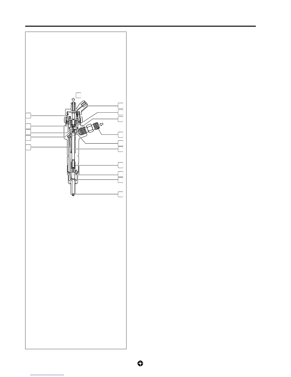
ELECTRO-INJECTOR
1.- Drive rod
2.- Spigot
3.- Injector
4.- Reel
5.- Pilot valve
6.- Spherical stopper
7.- Control area
8.- Supply chamber
9.- Control volume
10.- Fuel return
11.- Control conduct
12.- Fuel conduct
13.- Electrical connection
14.- Fuel inlet (high pressure)
15.- Spring
 Loading...