ENGINE REPAIR 6A-33
REMOVAL AND INSTALLATION OF INJECTION
PUMP
(mechanical injection engine)(mechanical injection engine)
(mechanical injection engine)(mechanical injection engine)
(mechanical injection engine)
CAUTION:
Before starting to remove, clean carefully all the
components to be removed or disconnect them as well
as surroundings.
Removal
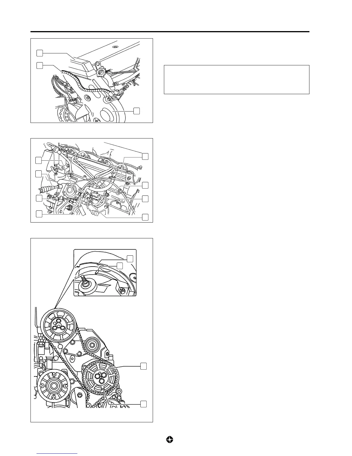
1) Remove generator and front support (see 6A-59).
2) Disconnect fixing braces of electrical wiring assembly (2).
3) Remove soundproofing upper cover (1) and timing front cover
(3).
4) Disconnect or remove:
• Pressure L.D.A. tube (8) in connecting point (4).
• K.S.B. device electric terminal (9).
• Electro stop device electric terminal (11).
• Linkages (6) and (7) from fuel supply and return pipes.
• Accelerator cable (5).
• Fuel injection rigid pipes (10); use recommended special
key ref. 790993.
5) Turn crankshaft till mark (A) of camshaft gear is aligned with
mark (B) of plungers lit. In this position, fit tool ref. 790965 in
hole (13) of the driving gear (12) and in hole at block placed
in front of (13); it this is not possible, turn the crankshaft two
complete turn till aligning slowly marks (A) and (B).
NOTE:
• Under these circumstances, piston of the cylinder n°
1 is T.D.C. position
• If the described synchronisation is not arrived at, this
will mean that there is a tensioning of timing belt or
some mis adjustment of same.
• If you intend to install the same pump, do two aligning
marks, one on the injecting pump housing and the
other on the auxiliary organs group houding. These
marks should be aligned when fitting again the pump.
1
2
3
A
B
12
13
4
5
6
7
11
10
9
8

 Loading...