6A-34 ENGINE REPAIR
6) Remove nuts fixing injecting pump and take it away.
NOTE:
The lower nut place near the block is removed with
key (F) ref. 790997.
CAUTION:
Plug with appropriate caps the conductions which
have been opened. Entry of some alien body in this
conductions could seriously damage the injection
system.
Installation and setting of injecting pump
1) Install injection pump in the appropriate place of auxiliary
organs group as follows:
• Check correct setting of timing (see operation 5
th
of removal).
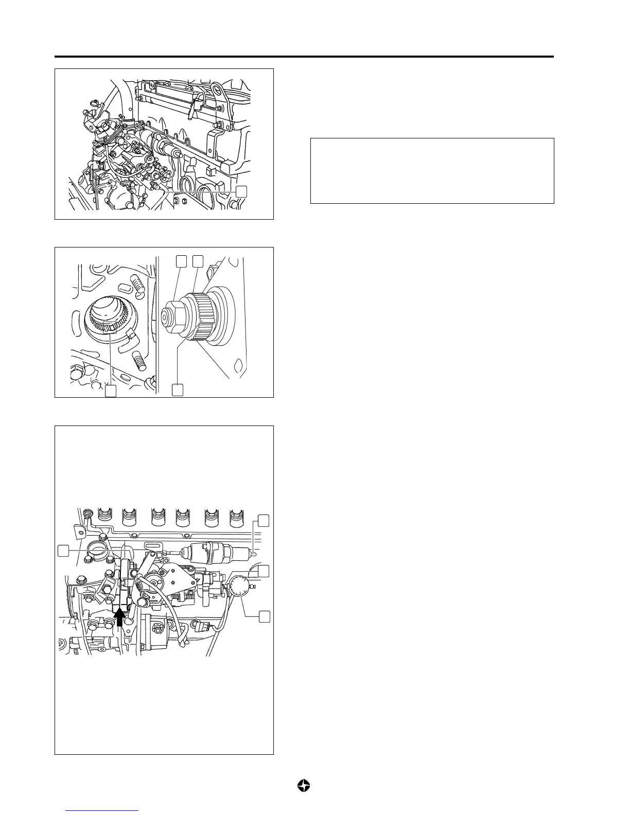
• Put front to front channelling (14) from drive shaft and the
guiding tooth (15) from hub (16) and install the pump.
NOTE:
If it is deemed to substitute pump hub (16), use tool ref.
790992 to keep in place the hub during removal or
installation of nut (17), and tool ref. 790991 to extract
hub.
Tightening torque for nut (17) of injecting pump grooved
hub: 8 Kg-m (80 Nm)
• Align marks ( ) to be found in the housing sump and in
the auxiliary organs group housing (if you are fitting the
same pump).
• Install nuts (18) fixing injecting pump without tighten too
much.
2) Inactivate K.S.B. device (9) supplying tension from the vehicle
during the setting up of pump.
NOTE:
The K.S.B. device is inactivated when the advancing
lever is not under loading.
3) Take away cap located in the pump closing screw and fit
adapter (C) ref. 790966; be sure that the tip is in contact
with the distributing piston. Install dial gauge (D) ref. 790967
in such a way that the measuring tip advances previously
some 3-mm.
4) Withdraw tool ref. 790965 which fixes the driving gear (12)
position of auxiliary organs group.
5) Turn slowly crankshaft in the opposite direction to rotation
till dial gauge (D) shows the L.D.C. of distributor piston;
then put into zero reading the dial gauge.
F
17
16
15
14
18
9
C
D
¨

 Loading...