ENGINE REPAIR 6A-35
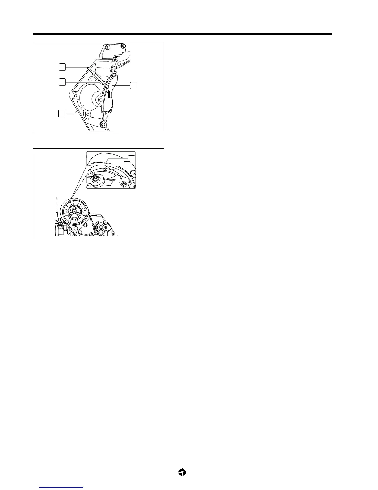
6) Fit tool (E) ref. 790965 in hole (20) of flywheel housing
(21). Turn slowly crankshaft in the same direction of
rotate while at the same time you press tool (E). Stop
turning when you notice that tool has found the milling
mark ( ) of flywheel (19).
Once this is done, the piston of cylinder n° 1 is in theT.D.C.
state and marks (A) and (B) from pulley and cover must be
aligned (cylinder n°1 valves closed). Otherwise, there is a
synchronisation failure because of faulty fitting of timing belt
or bad fitting of flywheel.
Also, under these circumstances, the distributor piston of
the injecting pump should have done a course 1,10
± 0,05
mm
as read in the dial gauge (D). If the course is different than
this, rotate injecting pump in its guiding till adjusting it to
the right value. Once this has been achieved, tighten nuts
fixing injecting pump applying the specified tightening torque.
To tighten lower nut, use key ref. 790997.
Distributor piston of injecting pump course:
1,10
± 0,05
mm
Tightening torque for nuts fixing injecting pump:
2,5 Kg-m (25 Nm)
7) Stop providing current to K.S.B. device.
8) Remove dial gauge (D) and adaptation tool (C). Install cap of
pump closing screw.
9) Withdraw synchronisation tool (E) for flywheel.
10) Continue installation reverse removal procedures applying
specified tightening torque and those specified in the
complementary tasks.
19
20
E
21
A
B
Tightening torques:
• Linkages for fuel injection pipes:
3,3 Kg m (33 Nm)
• Nuts of soundproofing upper cover:
0,5 Kg m (5 Nm)
• Screws at timing upper cover:
0,75 Kg m (7,5 Nm)
• Screw for supply or return linkages of fuel injecting
pump:
2,5 Kgm (25 Nm)
• Screw for linkage pressure pipe of L.D.A:
1 Kg m (10 Nm)
11) Carry out air purging of fuel supply circuit (see 6C-8).
¨

 Loading...