ENGINE REPAIR 6A-89
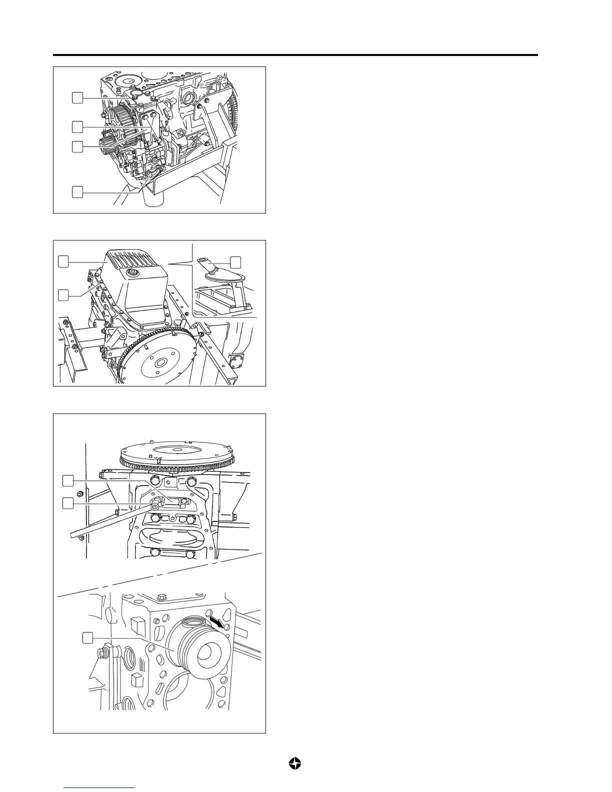
Left side
3) Dismantle screws (56) fixing the auxiliary organs group (55);
withdraw generator rear support of (57) and the auxiliary
organs group assembly (55).
NOTE:
• Plug adequately the oil passages of auxiliary organs
group. Entrance of alien bodies could damage
seriously the assembly.
• For GEAR BOX REPAIR, AUXILIARY ORGANS GROUP
AND OIL PUMP see 6A-63.
58
59
60
61
C
62
Lower part
4) Turn around the motor as seen in the drawing in such a way
that what was up is now down and what was down is now
up; remove the screws (59) and withdraw oil pan (58) with
gasket.
5) Remove the oil sucker (60).
Pistons and connecting rods
6) Place engine vertically as shown and dismantle the tool
preventing flywheel from turning.
7) Loose nuts of connecting rods covers by pairs (n° 1 - 4 and
n° 2 - 3),using appropriate key (C).
If the covers and pistons to remove are n° 1 and 4, place
these pistons in T.D.C..while for n° 2 and 3, place pistons in
L.D.C.
8) Remove screws and covers (61) and remove pistons (62)
with their connecting rods through the upper part of block.
NOTE:
• Make assemblies with pistons, connecting rods and
covers to maintain the positions of original assembly.
• If the half ball bearings are going to be used again
store them in such a way that the original mounting
positions keep identified.
57
56
55
56

 Loading...