ENGINE FUEL AND EMISSION CONTROL SYSTEM 6C-3
GENERAL DESCRIPTION
FUEL SYSTEM
(MECHANICAL INJECTION)(MECHANICAL INJECTION)
(MECHANICAL INJECTION)(MECHANICAL INJECTION)
(MECHANICAL INJECTION)
The fuel circuit for vehicles with mechanical injection engines is
made up of the following components:
• A fuel tank
• A fuel filter with incorporated primer and decanter of sedi-
ments
• A rotary mechanical injection pump with an automatic
advan-ce injection device for cold starts (KSB) and a varying
advan-ce system (LDA) depending on the pressure
generated by the turbocompressor in the intake manifold.
• Four mechanical injectors
• An electro-valve which controls the rate of fuel to the spark
plug at starting when the coolant or fuel temperature is
below 0ºC.
• A thermostarter spark pug attached at the intake manifold
which carries out pre/post heating when the ignition is on
and the coolant temperature is below 0ºC.
5
4
3
2
12
6
7
8
9
10
1
11
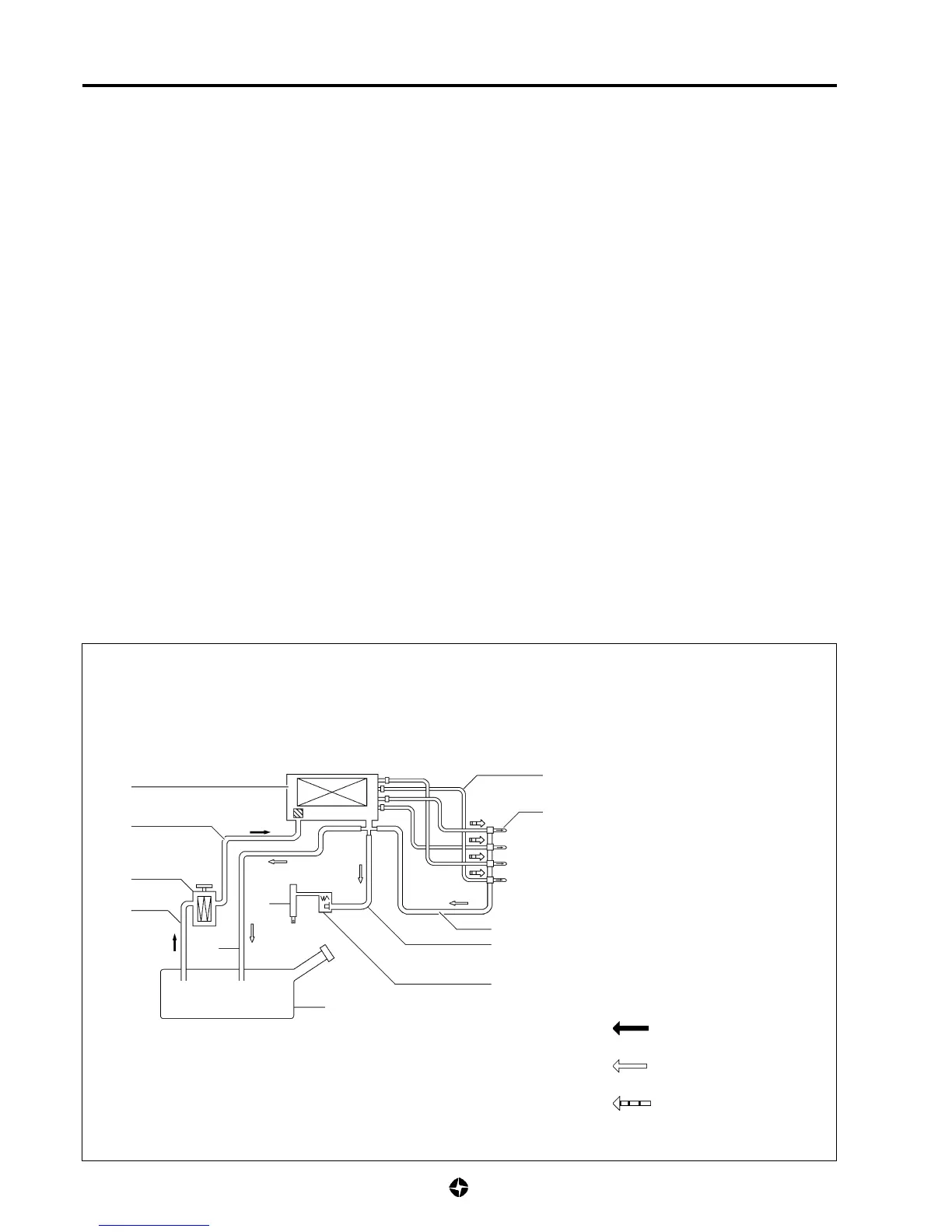
FUEL SYSTEM DIAGRAM
(MECHANICAL INJECTION ENGINES)
1. Fuel tank.
2. Fuel breather pipe.
3. Fuel filter, primer and decanter.
4. Breather pipe from filter to injector pump.
5. Injection pump.
6. Fuel injection pipes.
7. Fuel injectors.
8. Injector fuel return pipe.
9. Thermostarter fuel return pipe.
10. Thermostarter electro-valve.
11. Thermostarter spark plug.
12. General fuel return pipe to fuel tank.
Fuel feed
Fuel return
High pressure of fuel

 Loading...