12 Injection Port
12.3 Removing and inserting the glass insert
118
GC-2010 Plus
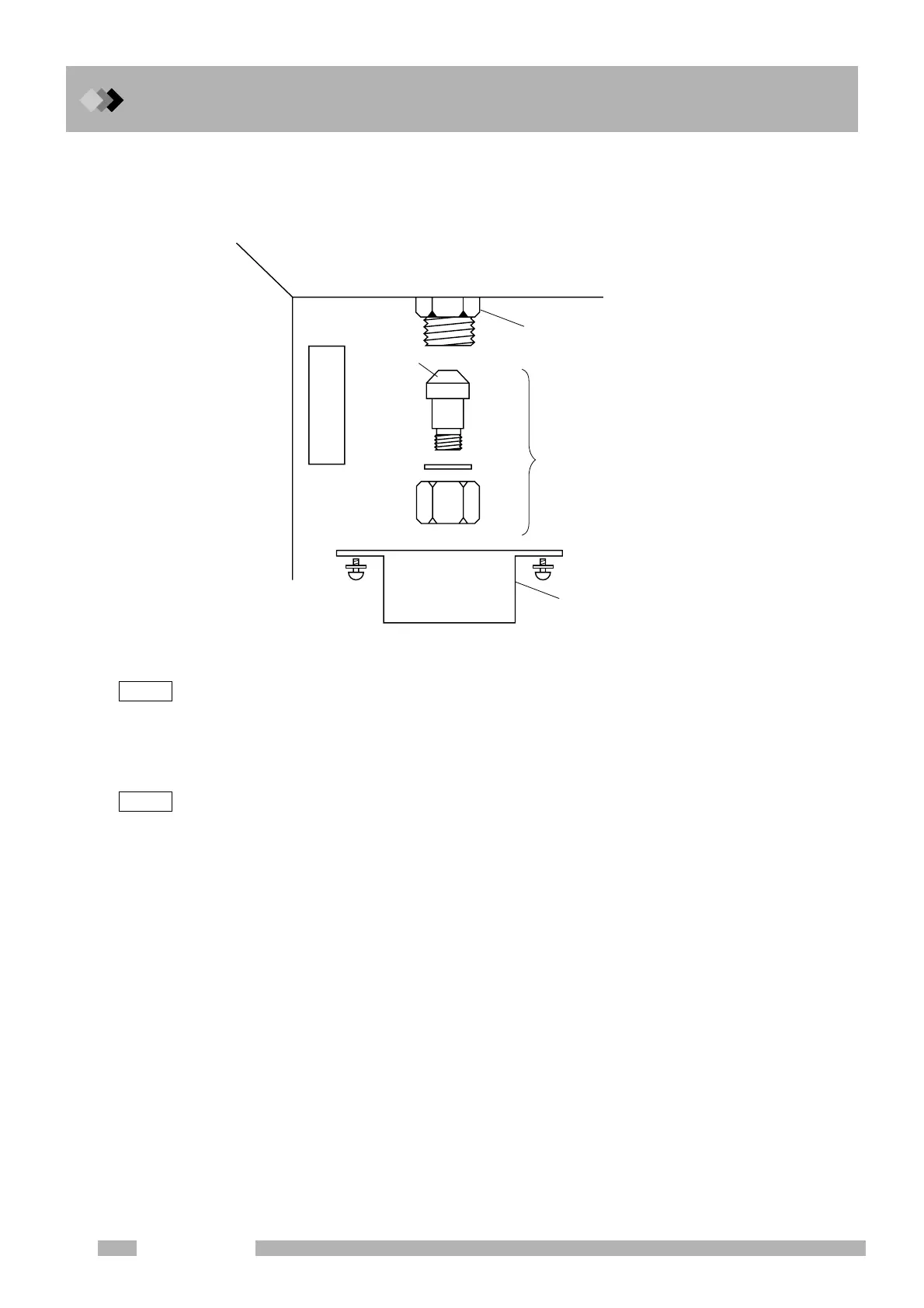
Q If the glass insert breaks in the injection port
If the glass insert breaks in the injection port, take out the thermal insulation cup and the
capillary adapter from within the oven and carefully remove the broken glass.
Fig. 12.3.7
NOTE Re-install the capillary adapter without allowing leaks.
If glass chips, etc. are present on the seal face, the seal may be damaged and leaks can occur.
Q Checking for injection port leaks
Leaks can negatively impact reproducibility of results, and can waste carreier gas.
NOTE Septum purge leaks do not affect performance. These error messages canbe cleaned.
(As for the following procedure, there could be cases in which the error message “purge leaks” etc.
appears. However, it does not matter to the test. Then select “Reset Error”.)
Check for leaks according to the following procedure.
(1) Turn off the system, and then turn on the system pressing “-” key and “0” key.
(2) Press [Start GC] (PF menu) from the [SYSTEM] key screen.
(3) Set the “Flow Control” to “Cont” from the [SYSTEM] key screen.
(4) Press [Stop GC] (PF menu) to stop the system temperature control.
(5) User the [MONIT] key to veryfy that the oven, injection portk and detector temperatures
have dropped below 40 °C.
(6) Press [Off] on the [FLOW] screen to stop AFC control. Carrier gas flow stops. Set the
purge flow tate to 0 ml/min.
(7) Remove the capillary column, and seal the connections with a new graphite ferrule (with
wire) and column nut.
(8) Install a blank nut (G-type) on both the split vent and purge vent.
(9) Verify that the gas cylinder pressure is above 300 kPa.
(10) Set the Split mode to “Direct” and Control mode to “Press” (from the [FLOW] key main
screen).
(11) Set the inlet pressure to 150 kPa and set the purge flow to 500 ml/min. Press [On/Off]
(PF menu) to start AFC control.
Capillary adapter
Injection port
Thermal insulation cup
Sealing
surface
Oven interior
Capillary adapter

 Loading...


