2 Installation
2.5 Power supply and wiring
18
GC-2010 Plus
Q Fuse
The following fuses are used in the GC-2010 Plus.
Q Allowing the GC to dry after transport.
Under some transport conditions, condensation may form inside the GC components. To
avoid injection port or detector heater unit short-circuits, allow the unit sufficient time to dry
after transport, and follow the procedure below after installation.
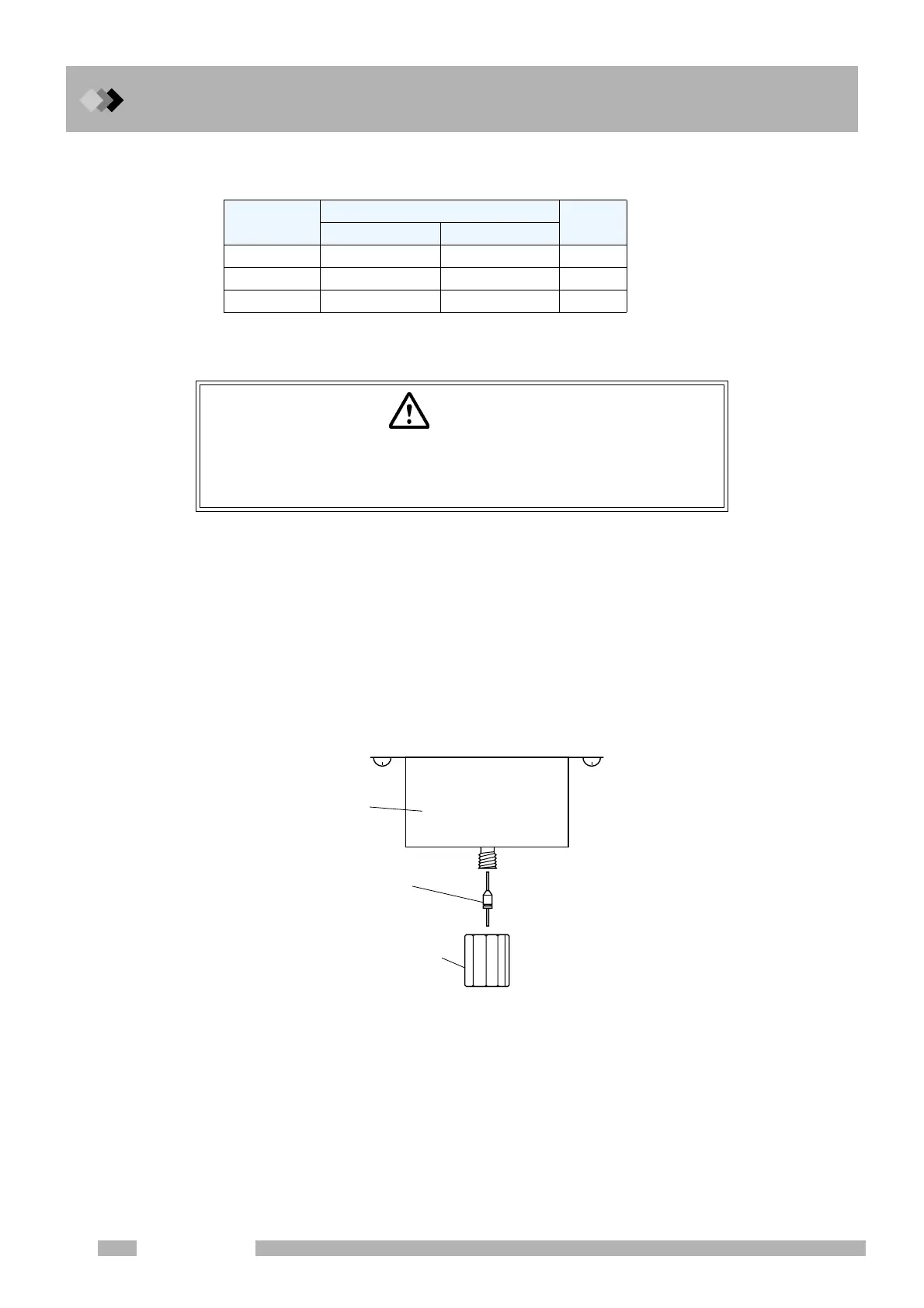
(1) Seal the injection port and column connections.
(2) Remove the injection ports and detectors from all configured analytical lines. (See “8.3
Specifying the Analytical Flow Line Components ([Line Config])”.)
(3) Set the column oven temperature to 300 °C, and start the GC. (See “11 Creating an
Oven Temperature Program” and “7 Starting and Stopping the GC [SYSTEM]”.)
(4) Keep the column temperature at 300 °C for 2 hours. (See “9 Monitoring the GC”.)
Fuse, No.
Rated current/voltage
Type *
∗Classification depending
on “IEC127”.
115 V model 230 V model
F1, F2 15 A / 250 V 10 A / 250 V T
F3, F4 5 A / 250 V 3.15 A / 250 V T
F5, F6 5 A / 250 V 5 A / 250 V T
CAUTION
GC-2010 Plus may get wet from humidity in some transport condi-
tions. In such case “drying-out” is necessary to avoid a short circuit at
the heater in the injection port or the detector.
Graphite ferrule
with a wire
Column nut
(or Column nut
of injection port)
Thermal
insulation cup

 Loading...


