Data Menu
Pocket-3D Reference Guide
3-50
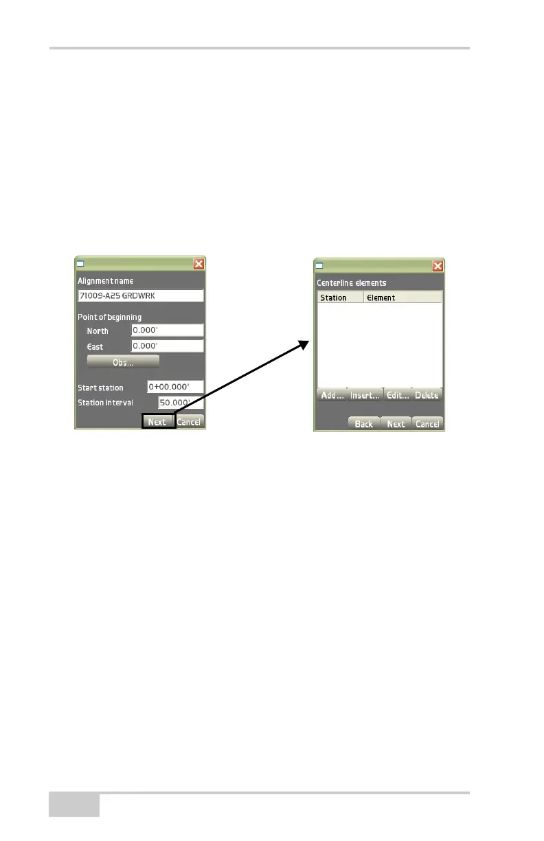
– North: enter the northing of the beginning point.
– East: enter the easting of the beginning point.
– Obs: measures the northing and easting of the beginning
point, instead of manually entering the values.
• Start station – enter the value for the starting station of the
alignment.
• Station interval – enter the value of the station interval of the
alignment.
Figure 3-72. Point of Beginning / Centerline Elements Dialog Boxes
The Centerline elements dialog box (Figure 3-73 on page 3-51) cre-
ates, edits, or deletes alignment elements. After creating station ele-
ments, press Next to create vertical profiles (Figure 3-73 on page 3-
51).
• Add – on the Centerline elements dialog box, press Add to enter
an element and its respective information, then press Ok to save
the information (
Figure 3-72).
– Element: select the type of element; either Straight, Curve
PC-PT, Spiral TS-SC, or Spiral SC-ST.
– Start station: the starting station displays at the interval set for
each element.
– Start azimuth: enter the starting azimuth. This field is only
available for the first element.
– Length: enter the length of the element.