Technical data
168 Manual m600 basic 2.6_01
14
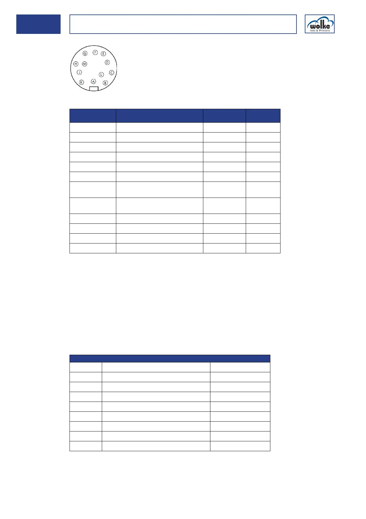
Top view of the solder side of the plug
Pulse generator
socket
Tab. 14_15: Connector pin assignment – pulse generator socket
Technical data - pulse generator
The output signal of the pulse generator must be a rectangular pulse sig-
nal. This signal input on the m600 basic is equipped with a pullup resistor
against +5V. It is sufficient if the primary detector can only drive the out-
put signal actively to ground (0 Volt = "Low level") (open collector out-
put). If the primary detector used can also be actively run on a "high level"
(+5 V), the output voltage must not exceed +5.5 V.
The following table contains the specifications for the pulse generator con-
nection.
Tab. 14_16: Specifications for the pulse generator connection
Cable connector
Cable tie, series 423, Typ 99-5629-15-12
Pin on the
m600 basic
Function Values m600
basic
I/O
A-
BGND 0VDC -> O
C Output signal A <- I
D GND (jumpered in plug)
E Output signal A, inverted <- I
F-
GVcc +5VDC
max. 0,5 A
-> O
H Output signal B, (90° out of
phase)
<- I
J GND (jumpered in plug)
K Output signal B, inverted <- I
L
M
Properties of the pulse generator output signal (pulse)
V
max.
Maximum output voltage max. 5,5 V
V
L
Output voltage pause ("Low level") 0...0,8 V
V
H
Output voltage pulse ("High level") 2,0...5,5 V
I
out
Output current min. 5 mA
t
p
imp Signal length of pulse min. 200 ns
t
p
pa Signal length of pause min. 200 ns
Rimp-pa Ratio of pulse to pause 10 %...90 %
Rimp/m Ratio of pulse/meter 5000...15000 Imp/m
f
max
max. pulse frequency 30 kHz