Installation
18 Manual m600 basic 2.6_01
4
Position of
photoelectric
cell
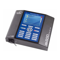
Fig. 4_33: Position of photoelectric cell
This form of installation enables the standard values for the sensor dis-
tance to be maintained for both product path directions, see "Settings/
Installation/Print head1/2".
Installing the
photoelectric
cell
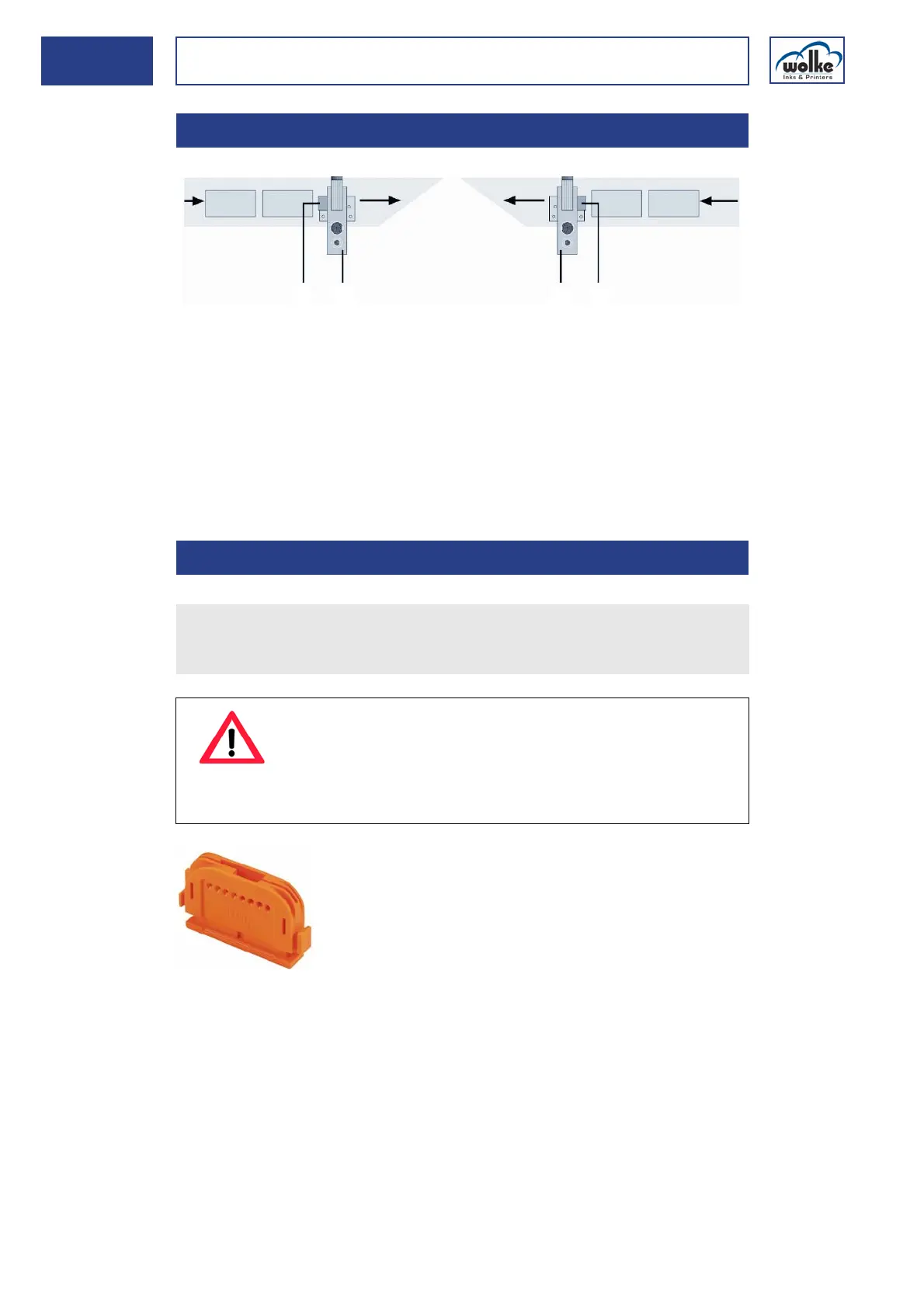
Fig. 4_34: Cutter for optical fibre
4.4.1 Position of photoelectric cell
1 Photoelectric cell 2 Print head
4.4.2 Installing the photoelectric cell
11
2
2
Path of product from right to left
Path of product from left to right
Use the cutter to cut the optical fiber to the required length.
When taking the measurements, please note that the two upper ends
of the optical fiber have to be inserted in the photoelectric cell later.
ATTENTION
If the optical fiber is not cut cleanly, this may impair the
operation of the photoelectric cell.
Therefore: Only use each cutting hole in the cutter once.
Every new optical fiber comes with a new cutter.