Technical data
Manual m600 basic 2.6_01 175
14
Print head
socket
As two print heads can be activated simultaneously via the m600 basic.
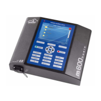
Plug-and-socket connectors used
A 16-pole plug-and-socket connector is used for the print head connec-
tion.
Top view of the solder side of the plug
Photoelectric
cell on the print
head of the
m600 basic
The connector cable between the controller and the print head is divided
on the print head for two different function areas. 13 strands are connect-
ed to the HP Pendriver board and three strands to the socket.
The output on the standard photoelectric cell is equipped with a NPN tran-
sistor (open-collector). This means that the output signal is an inactive
high-resistance one and is drawn from ground (0 Volt) in the active state.
Given that in the m600 basic, this signal is connected internally to a pullup
resistor against +5 Volt, the signal level received by the m600 basic is ei-
ther 0 Volt (active) or +5V (inactive).
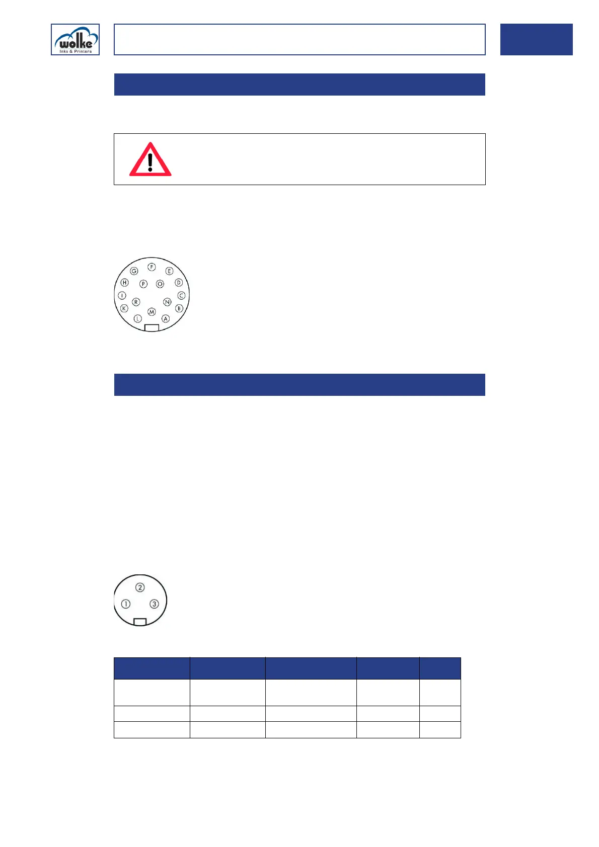
Plug-and-socket connectors used
A 3-pole plug-and-socket connector is used for the connection.
Top view of the solder side of the plug
Tab. 14_22: Pin assignment of the photoelectric cell
14.2.5 Print head socket
ATTENTION
Only screw-fasten or remove the print head cable with
the m600 basic either switched off or in "Stop" mode.
14.2.6 Photoelectric cell on the print head of the m600 basic
Cable connector
Cable tie, series 723, Typ 09-0505-70-16
PIN on the
m600 basic
Function Values m600 basic Cable colour I/O
1 Output signal of
photoelectric cell
GND
(0 V DC)
black <-
2Vcc+24VDCbrown->
3GNDGround (0V)blue->
Cable connector
Cable tie, series 712, Typ 09-0405-00-03