Technical data
172 Manual m600 basic 2.6_01
14
External inputs
and outputs
Description of functions
The m600 basic has 4 digital inputs and outputs. The inputs can be used
to trigger a diversity of m600 basic functions. The outputs indicate various
items of information about the status of the m600 basic. The relevant set-
tings have to be made in the "Settings/System configuration/Ext. Inputs"
menu. To protect the m600 basic's electronics, all input and output chan-
nels in the panel socket are decoupled via optocouplers.
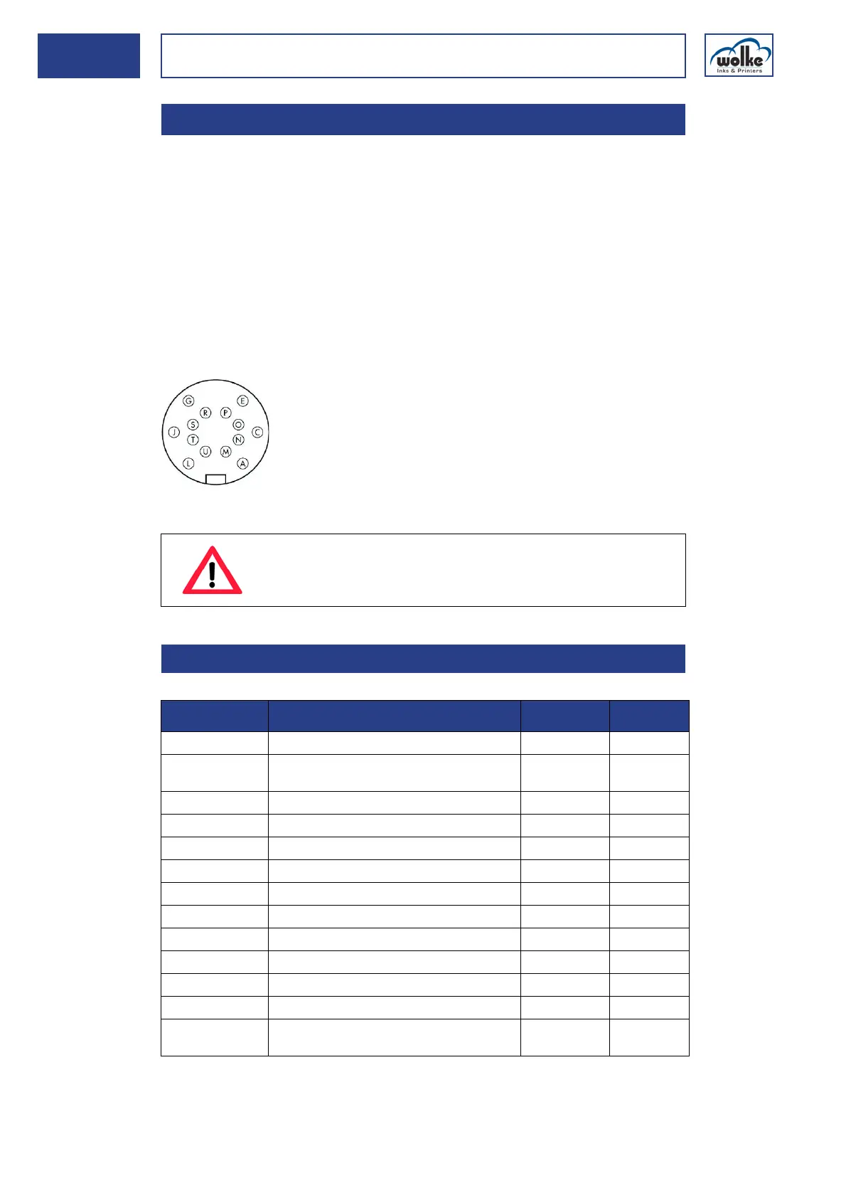
Plug-and-socket connectors used
A 14-pole plug-and-socket connector is used for the external input and
output connections.
Top view of the solder side of the plug
24 V DC socket
Tab. 14_18: Connector pin assignment of the 24 V DC I/O socket
14.2.4 External inputs and outputs
ATTENTION
During switching ON or OFF, all 4 outputs of the m600 ba-
sic are temporarily activated.
14.2.4.1 24 V DC socket version
Cable connector
Cable tie, series 423, Typ 99-5651-15-14
PIN on the
m600 basic
Function Cable colour I/O
P m600 basic 24 V DC white/yellow ->
JExt. +24VDC
(for the outputs)
black <-
T m600 basic GND brown ->
A Ext. GND (for the outputs) gray <-
C Input 1 m600 basic pink <-
G Input 2 m600 basic red <-
L Input 3 m600 basic purple <-
N Input 4 m600 basic white/green <-
E Ext. GND (for the inputs) blue <-
O Output 1 m600 basic, OK green/brown ->
R Output 2 m600 basic, Error yellow/brown ->
S Output 3 m600 basic; ink level below 10% white ->
U Output 4 m600 basic
Count value reached or end of printing
yellow ->