Installation
Manual m600 basic 2.6_01 25
4
To ensure the pulse generator transmits the correct product speed, as far
as possible, the following must be considered:
• Install the pulse generator as close to the print heads as possible (ideally in
the same track).
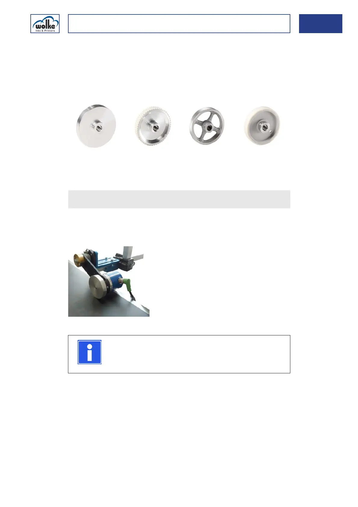
• Use the correct measuring wheel (aluminium/rubber/plastic) in order to
achieve speed measurements without slippage.
Fig. 4_39: Various measuring wheel versions
Installation of
the external
pulse generator
For optimum contact between the pulse generator and the conveyor belt,
a resilient pulse generator mount can be used (optional).
This mount enables the position and pressing pressure to be adjusted.
Fig. 4_40: Resilient pulse generator mount
Solid aluminium,
smooth (standard)
Aluminium with stud-
ded rubber cover
Solid aluminium
with cross spokes
Plastic, smooth
If you use a different pulse generator, please refer to Chapter 6.2.1,
"Pulse generator/Pulses/Speed"!
NOTE
Ideally you should avoid mounting the pulse generator on
the belt shaft or on the underside of the conveyor belt.
The speeds can well be different here.