Installation
Manual m600 basic 2.6_01 9
4
Fig. 4_15: Measuring wheels for pulse generator
Fig. 4_16: Resilient pulse generator mount
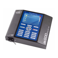
Fig. 4_17: Pulse generator cable
Accessories
Fig. 4_18: Warning beacon
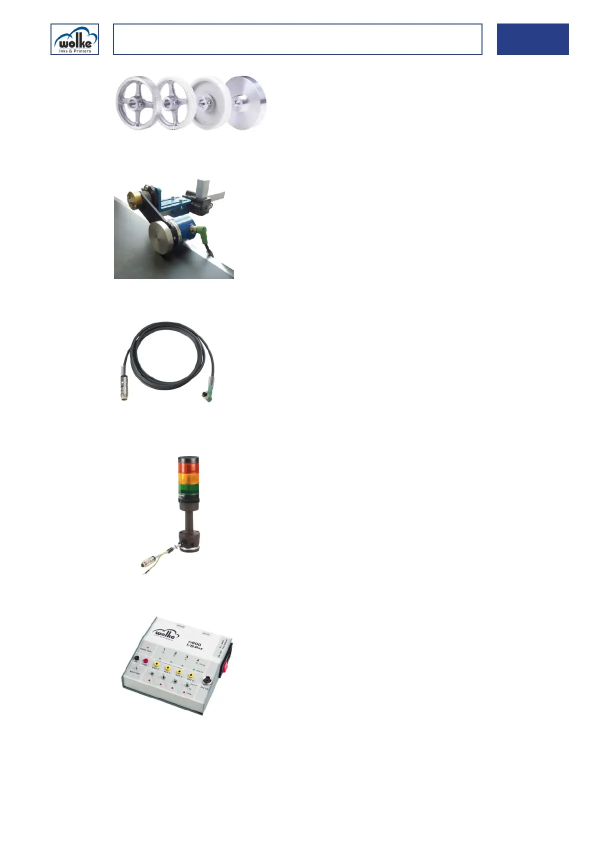
Fig. 4_19: I/O-Box
Pulse generator measuring wheels
for the different conveyor belt sur-
faces.
This easy to install mount ensures
that the pulse generator is perfectly
supported.
Connector cable between the pulse
generator and controller.
The warning beacon is mounted di-
rectly on the m600 basic and is for
indicating system faults. (for hard-
ware version m1.21)
This simulation box is for internal
test purposes only (it is for checking
the four outputs and inputs and for
testing the BCD function).