Installation
Manual m600 basic 2.6_01 21
4
Settings of
photoelectric
cell
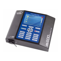
Fig. 4_36: Adjusting photoelectric
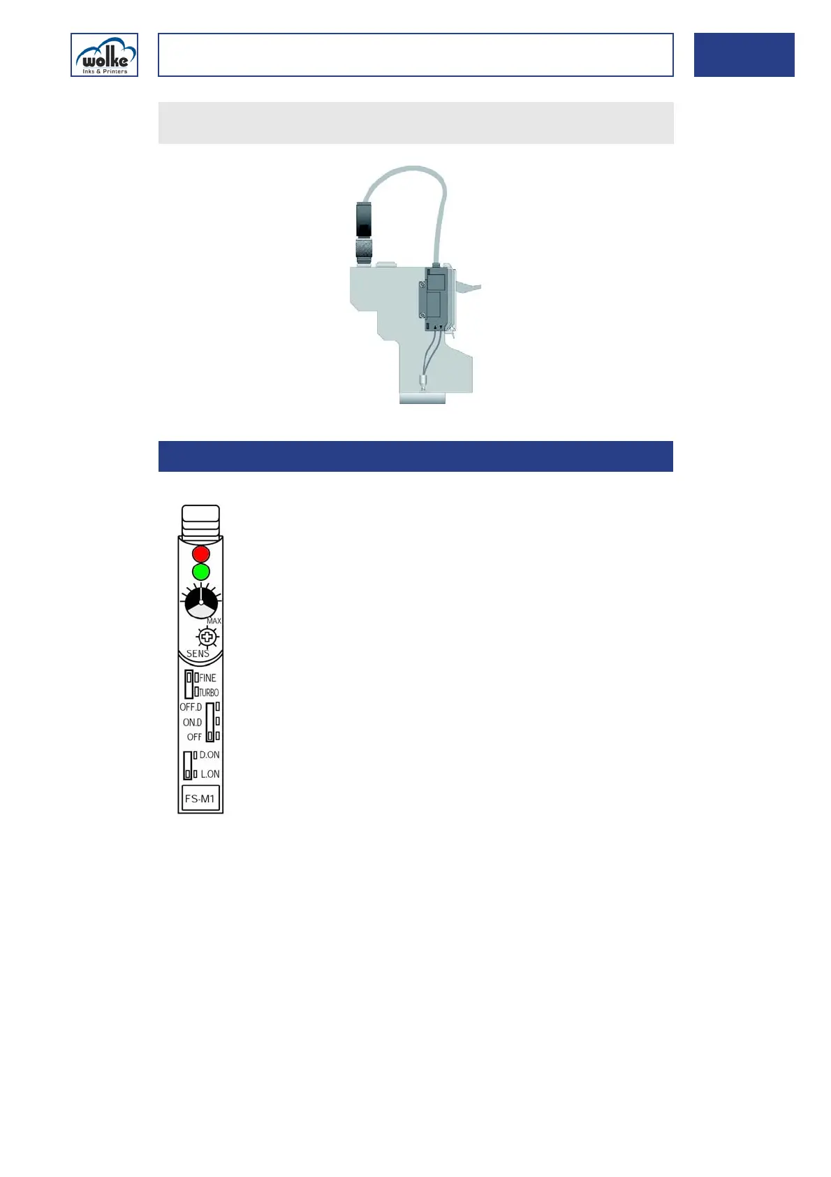
Active indicator (red)
Lights up when the switch connection is activated.
Stability indicator (green)
Lights up when sufficient light is received.
Indicator
Shows the current position of the sensitivity trimmer. One turn of the
trimmer changes the position of the indicator by one mark on the indicator
scale.
Insert the connector of the photocell cable into the socket on the
print head provided to this effect, and tighten the connector by hand.
4.4.3 Settings of photoelectric cell
Active indicator (red LED)
Stability indicator (green LED)
Sensitivity trimmer
FINE/TURBO selector switch
Output timer selector switch
Output selector switch
Indicator