Installation
Manual m600 basic 2.6_01 29
4
Description of functions
The springs included in delivery have different tensile strengths. The dif-
ferent attachment positions are for weight compensation for 1- and 2-
head systems and for adjusting the spring force in the case of vertical
printing.
The locating wheel or the deflector moves the parallelogram to the correct
position and thereby facilitates initial distance compensation which goes
easy on the material.
The choice between the deflector and locating wheel will depend on the
specific application.
Installation by
means of the
parallelogram
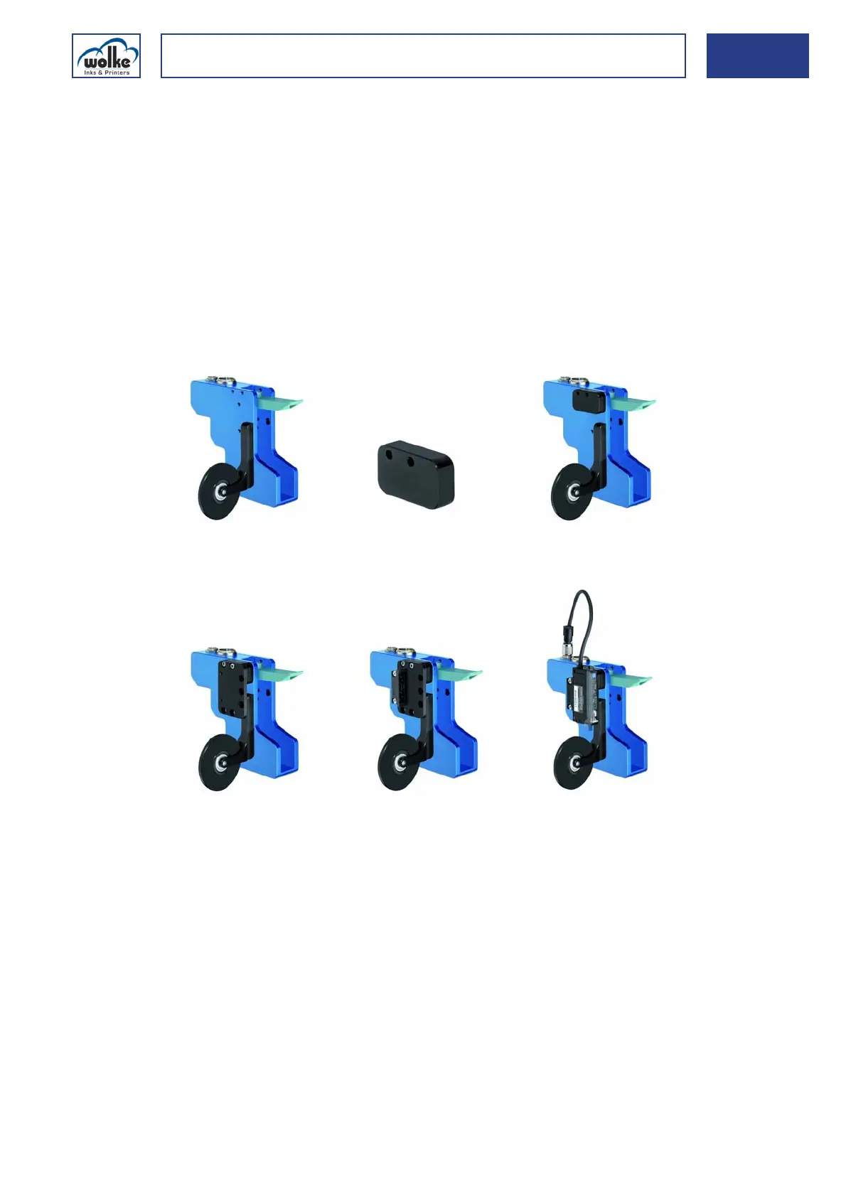
Installation of the locating wheel (with the new sensor)
If a locating wheel is used, the new sensor has to be installed on the print
head as follows (because of its dimensions):
The locating wheel is
screwed on as before with
two size M3 screws (6 mm
long).
New spacer plate.
Fit the spacer plate.
Fasten the adapter and
spacer plate (two size M3
screws, max. 15 mm long).
Screw on the installation
mount.
Attach and connect the
sensor.