Error Troubleshooting
Xerox Internal Use Only Phaser 6600 and WorkCentre 6605
Service Manual
2-221
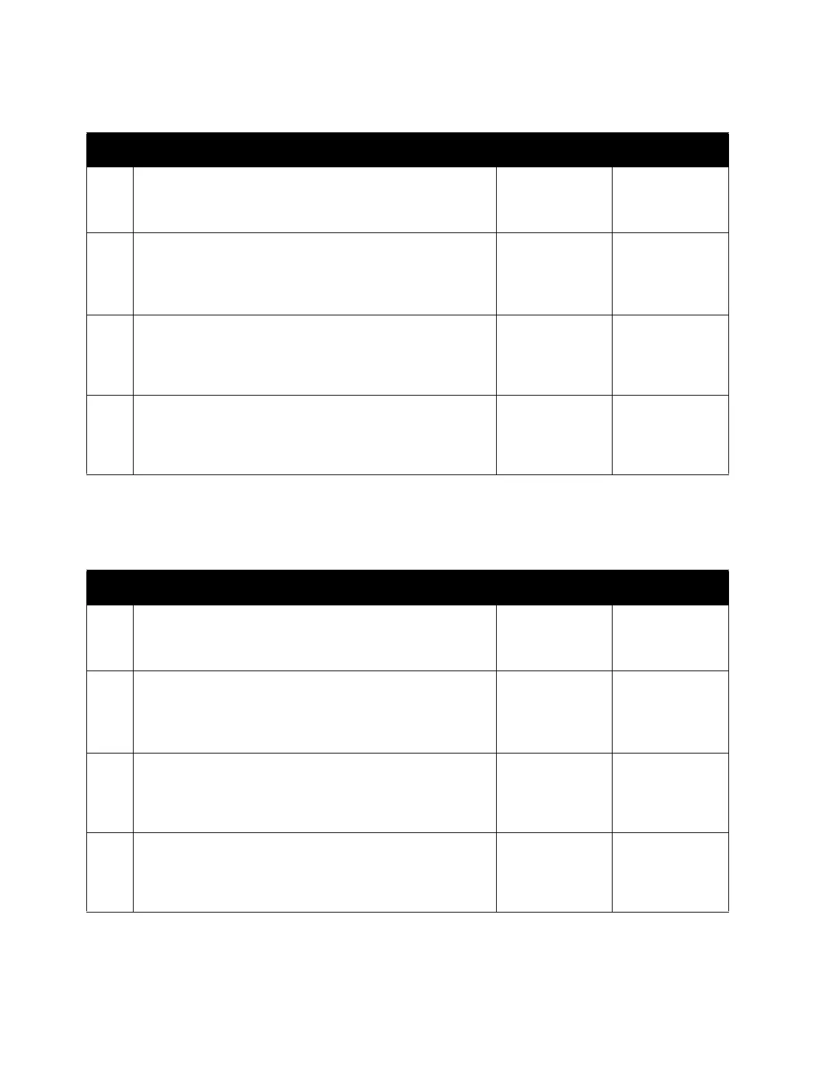
Exit Clutch 1 [Exit Drive Assembly] (PL17.1.21)
Exit Clutch 2 [Exit Drive Assembly] (PL17.1.21)
Step Check Yes No
Possible causative parts:
• Exit Clutch 1 [Exit Drive Assembly] (PL17.1.21)
• MCU Board (PL18.1.13)
1 Check the Exit Clutch 1 operation
Execute Digital Output diagnostic test 071-011, and check
the Exit Clutch 1 operation.
Does the Exit Clutch 1 function normally?
Replace the MCU
Board.
Go to step 2.
2 Check the Exit Clutch 1 connection
Check the connection between the Exit Clutch 1 and the
MCU Board.
Is P/J40 connected securely?
Go to step 3. Connect P/J40
securely.
3 Check the power to the Exit Clutch 1 (+24 VDC)
Close the interlock switch(es), and check if the voltage
between the MCU Board ground and the P/J40-1 pin is about
+24 VDC.
Replace the Exit
Clutch 1.
Refer to
“+24 VDC Power
FIP” on
page 2-222.
Step Check Yes No
Possible causative parts:
• Exit Clutch 2 [Exit Drive Assembly] (PL17.1.21)
• MCU Board (PL18.1.13)
1 Check the Exit Clutch 2 operation
Execute Digital Output diagnostic test 071-012, and check
the Exit Clutch 2 operation.
Does Exit Clutch 2 function normally?
Replace the MCU
Board.
Go to step 2.
2 Check the Exit Clutch 2 connection
Check the connection between the Exit Clutch 2 and the
MCU Board.
Is P/J38 connected securely?
Go to step 3. Connect P/J38
securely.
3 Check the power to the Exit Clutch 2 (+24 VDC)
Close the interlock switch(es), and check if the voltage
between the MCU Board ground and the P/J38-1 pin is about
+24 VDC.
Replace the Exit
Clutch 2.
Refer to
“+24 VDC Power
FIP” on
page 2-222.
 Loading...