Connecting ACPower to theSH4R Shelf
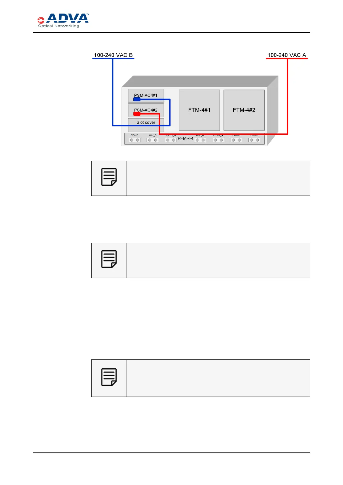
Figure 70: 1+1 Configuration Wiring
For improved cooling, install an appropriate slot cover in the empty PSM
slots.
4. Based on your configuration, identify the PSM-AC4 that will be connected first.
5. Insert the AC power coupler into the receptacle on the PSM-AC4.
6. Insert theACpower cable plug into the dedicated ACpower source outlet.
The ACpower cable plug serves as the main disconnection device.
Therefore, the dedicated AC power outlet must remain accessible so as
to be readily operable for use.
7. Repeat this procedure for each power cable needed for your configuration.
8. If the dedicated AC power source outlet has a power switch, set it to the ON (|)
position to power on the system for the first time.
As soon as power is up, the ECM-2 starts booting. The Mod LED of the first PSM-
AC4 should turn green, indicating that the units are functioning properly.
The FTM-4s should start working, one after another and the Svc LED should turn
green. This also indicates that the FTMs are functioning properly. In addition, the
Mod LEDs of all modules installed in the shelf should turn green.
If the Mod LED of the PSM-AC4 is off, then no power is being supplied to
the unit. In case of an error, the Mod LED turns red. For troubleshooting
information, see the FSP 3000 C Troubleshooting Guide or contact ADVA
Optical Networking for technical assistance.
9. If necessary, repeat this procedure for each SH4R mounted in the rack.
FSP3000 C Hardware Guide - R1.1 - Issue:A (12/09/2016) 241