128 Chapter 9
Communication with External Equipment (Using the I/O Ports)
Using the I/O Ports
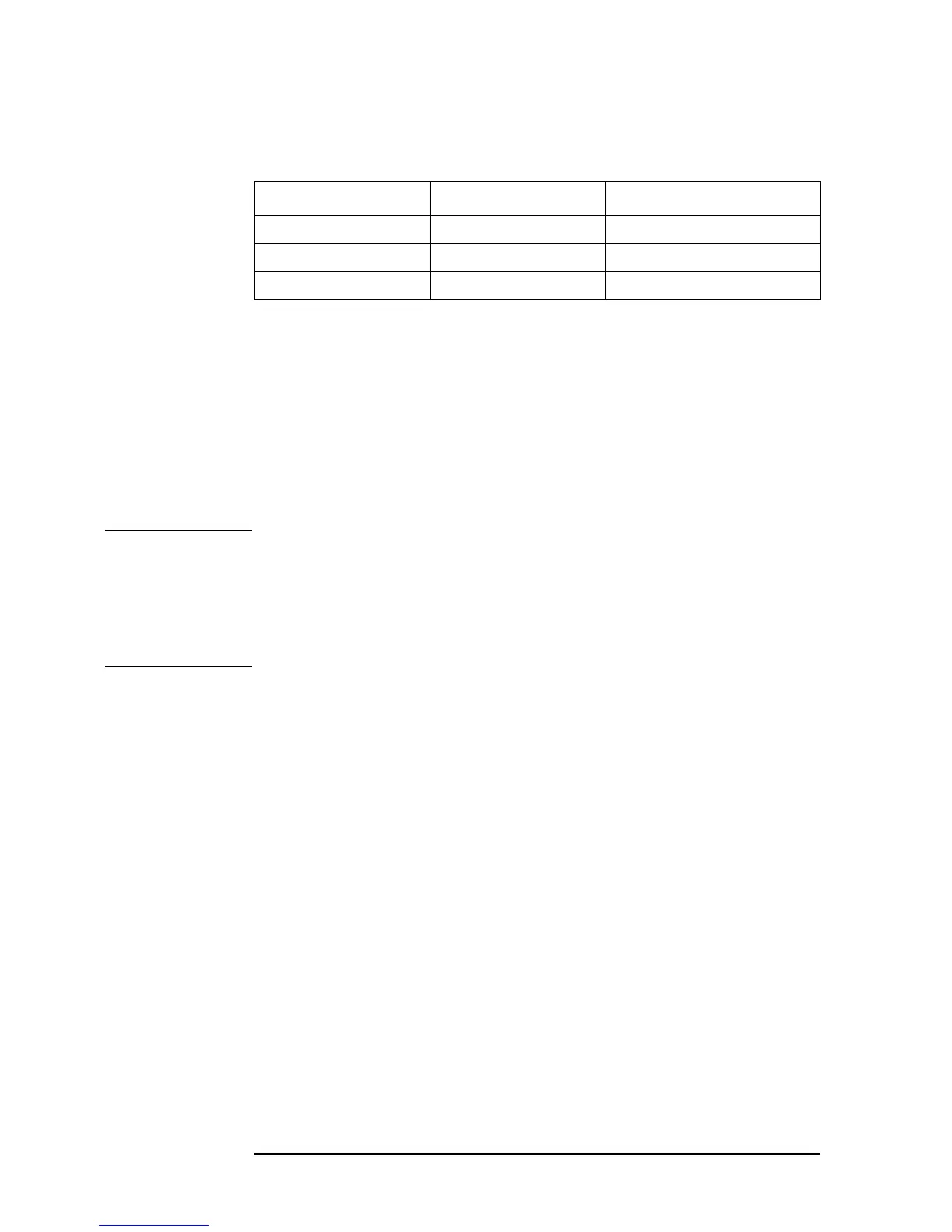
To read out data from each input port (C to E) to the controller, use the following
commands.
To use ports C, D, and E as input ports, use the following commands to set ports C and D as
input ports in advance.
• “CIN” on page 278
• “DIN” on page 297
To select positive logic or negative logic for input/output signals of ports, use the following
commands. You can save this setting into an instrument setup file using the save function.
• “NEGL” on page 362
• “POSL” on page 403
NOTE The above commands, used to change the positive logic/negative logic setting, are
available for the following ports.
• Output ports A to H
• Input ports C to D
• PASS/FAIL signal
To make the setting so that OUTPUT1 and OUTPUT2 goes HIGH (or LOW) when a pulse
is inputted into INPUT1, use the following commands.
• “OUT1ENV{H|L}” on page 367
• “OUT2ENV{H|L}” on page 368
To set OUTPUT1 and OUTPUT2 to HIGH (or LOW), use the following commands.
• “OUT1{H|L}” on page 367
• “OUT2{H|L}” on page 368
To check that any pulses have been inputted to INPUT1, use the following command.
• “INPT?” on page 319
GPIB command Instrument BASIC command Description
“OUTPINPCIO?” on page 381 “READIO(16,2)” Reads out 4-bit width data from port C.
“OUTPINPDIO?” on page 382 “READIO(16,3)” Reads out 4-bit width data from port D.
“OUTPINPEIO?” on page 382 “READIO(16,4)” Reads out 8-bit width data from port E.
 Loading...


