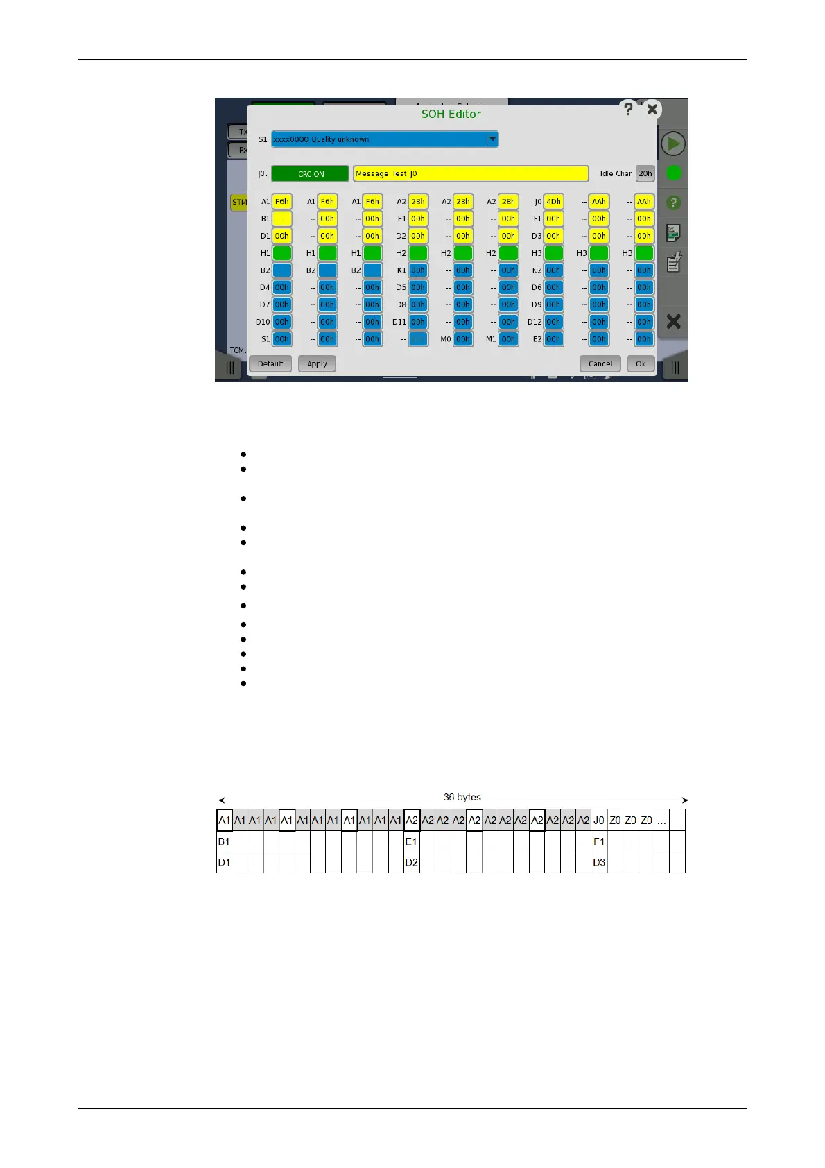
POH Editor
The setup principle is the same in this editor dialog as in the SDH structure.
Touching a button or opening a drop-down menu will open for new editor
dialog boxes, new value selections etc.
S1: Synchronization status
J0: Regenerator section trace
Idle Char is an Ascii code used for the padding.
A1, A2: Framing
Defined A1 as F6h (1111011b), A2 as 28h (00101000b).
B1: BIP-8 (Bit Interleaved Parity) This byte cannot be set.
E1, E2: Orderwire
E1 is part of the RSOH, E2 is part of the MSOH.
F1: User channel
D1-D3: RS (Regenerator Section) data communication channel (DCC
R
)
D4-D12: MS (Multiplex Section) data communication channel (DCC
M
)
B2: BIP-N×24 These bytes cannot be set.
K1, K2(bit 1 to bit 5): Automatic protection switching (APS) channel
K2(bit 6 to bit 8): MS-RDI (Multiplex Section Remote Defect Indication)
M0, M1: MS-REI (Multiplex Section Remote Error Indication)
H1, H2, H3: AU-n pointer These bytes cannot be set.
This editor format is the same as SOH of STM-1. For STM-4/16/64, SOH bytes
in other column are filled with value set by the editor. In case of STM-4 SOH
in following figure, you can edit A1A2 bytes in thicker lines cell. The bytes in
gray cell are filled with the value in left side cell in thicker lines.
Touching a POH button launches the VC-x POH Editor dialog box. The
contents of the dialog box depends on which path overhead you are
configuring.