AP Servo Installation, Configuration, and Calibration
SkyView System Installation Guide - Revision AA 10-11
Servo Electrical Installation
Dynon Avionics’ servos are supplied with 7 unterminated wires, each about 8” in length. We
recommended that you use the SV-NET-SERVO (one per servo) network cabling kit when
installing servos; however, it is ultimately the responsibility of the installer to decide on
connectors and associated wiring.
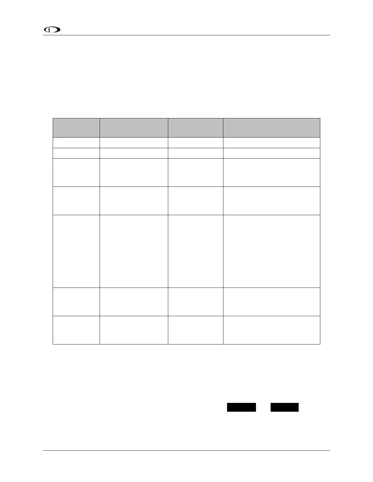
Table 74 describes servo wire colors, and pins for DB9 connectors supplied in the SV-NET-
SERVO Kit.
Connected in parallel with
other SkyView Network
devices
Connected in parallel with
other SkyView Network
devices
AP
Disengage/Control
Wheel Steering
(CWS) Button
Connected through a
normally-open pushbutton
switch to Ground (disengages
AP when button is pushed). If
two servos are installed, the
yellow wire from each servo is
connected in parallel to a
single pushbutton.
Connected in parallel with
other SkyView Network
devices
Connected in parallel with
other SkyView Network
devices
Table 74 – SV-NET-SERVO; Detailed Servo Wiring
Circuit Breaker/Fuse
We recommend that electrical power for the autopilot servos be protected with an
appropriately sized circuit breaker or fuse that is accessible to the pilot while in flight.
SkyView continuously communicates with the servos even when the autopilot is disengaged. If
SkyView is operating, but the servos are not receiving power, PTCH ERR and ROLL ERR will be
displayed in Red on the top bar (AP STATUS area, to the left of the clock). Therefore, we
recommend that the servo power wiring be designed to receive power whenever SkyView is