Configuring the ECN330-switch
320 1553-KDU 137 365 Uen D 2006-06-16
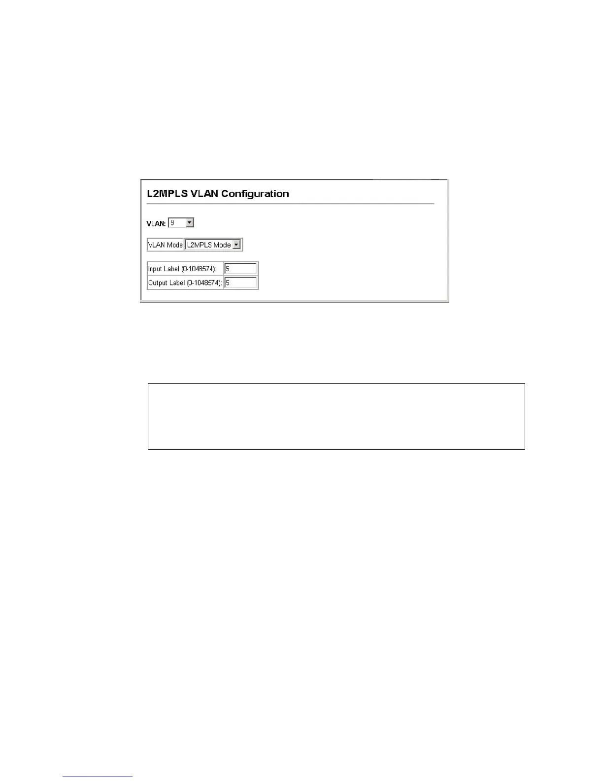
Web – Click L2MPLS, VLAN Configuration. Specify the VLAN that will be bound
to the L2MPLS tunnel, set the status to enabled, set the mode to L2MPLS, and
enter the input and output labels, then click Apply.
Figure 128 L2MPLS VLAN Binding
CLI – The following example configures VLAN 9 to operate as an L2MPLS
tunnel, and associates the MPLS input and output labels with the VLAN.
6.13.2 Configuring an MPLS Uplink Port
Use the L2MPLS Port Configuration page to set the operational characteristics
for an MPLS uplink port.
Command Attributes
• Port – Port number. (Range: 1-27)
• Status – Configures a port to enter L2MPLS uplink port mode.
• Tunnel Label (0-255)) – Sets the MPLS tunnel label that will be used to
construct the MPLS header on the L2MPLS uplink port. This label is
used by switches within the MPLS core network to establish a path from
the entry point to the exit point. (Range: 0-255)
• VC Label (0-1048574) – Sets the MPLS port-based virtual channel
(VC) label. All incoming packets forwarded to MPLS ports will use this
Console(config)#interface vlan 9
Console(config-if)#mpls l2
Console(config-if)#exit
Console(config)#mpls static binding vlan 9 input 5 output 5
Console(config)#