Configuring the ECN330-switch
3211553-KDU 137 365 Uen D 2006-06-16
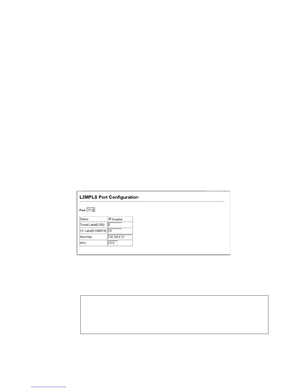
VC to generate MPLS labels. The VC is used to map traffic to a specific
customer port on the edge switches at the boundaries of the MPLS
network. (Range: 0-1048574)
• Next Hop – Configures the next hop MPLS switch/router IP address.
This IP address will be used to identify the next hop across the MPLS
network or, more commonly, the edge switch where traffic is passed on
to the customer.
• MTU – Specifies the Maximum Transfer Unit (MTU) size for the specified
port. (Range: 1500-9216 bytes)
The MTU setting for the uplink port takes precedence over the System
MTU (see “Configuring the Maximum Frame Size” on page 72). Also,
note that if the MTU setting for the uplink port has been specified, then
setting the system MTU will not change the port MTU.
Web – Click L2MPLS, Port Configuration or Trunk Configuration. Configure the
operational characteristics for the L2MPLS uplink port, and click Apply.
Figure 129 Configuring an L2MPLS Uplink Port
CLI – The following example configures port 25 as an L2MPLS uplink port, and
then specifies the tunnel label, the VC, the next hop, and the port MTU.
Console(config)#interface ethernet 1/25
Console(config-if)#mpls tunnel 5
Console(config-if)#mpls vc 10
Console(config-if)#mpls next-hop 192.168.0.19
Console(config-if)#switchport mtu 1518
Console(config-if)#