192
SYNCHRO IN SEL Default
FRAME ─ 0
LINE
SDI1, 2 1
Composite (525/60) 3
Composite (625/50) 4
Component (Y/C) 4
Component (others) 1
AVDL
SDI1, 2 1
Composite (525/60) 3
Composite (625/50) 4
Component (Y/C) 4
Component (others) 1
INPUT
SDI1, 2 0
Composite (525/60) 2
Composite (625/50) 3
Component (Y/C) 4
Component (others) 1
HD Phase
*1
Parameter Default Setting range (Steps) Description
1080 H Phase 0 clk
-1375 - 1375 clk
(1 clk)
Adjusts the horizontal and vertical
phases of the system referring to
genlock signal. This setting is
applied to 1080-format output
signals.
1080 V Phase
0 Line
*1
(Frame, Input)
1 Line
*1
(Line, AVDL)
-563 - 563 Lines
(1 Lines)
720 H Phase 0 clk
-2063 - 2063 clk
(1 clk)
Adjusts the horizontal and vertical
phases of the system referring to
genlock signal. This setting is
applied to 720-format output
signals.
720 V Phase
0 Line
*1
(Frame, Input)
1 Line
*1
(Line, AVDL)
-375 - 375 Lines
(1 Lines)
*1 These settings cannot be made if there is no reference signal input.
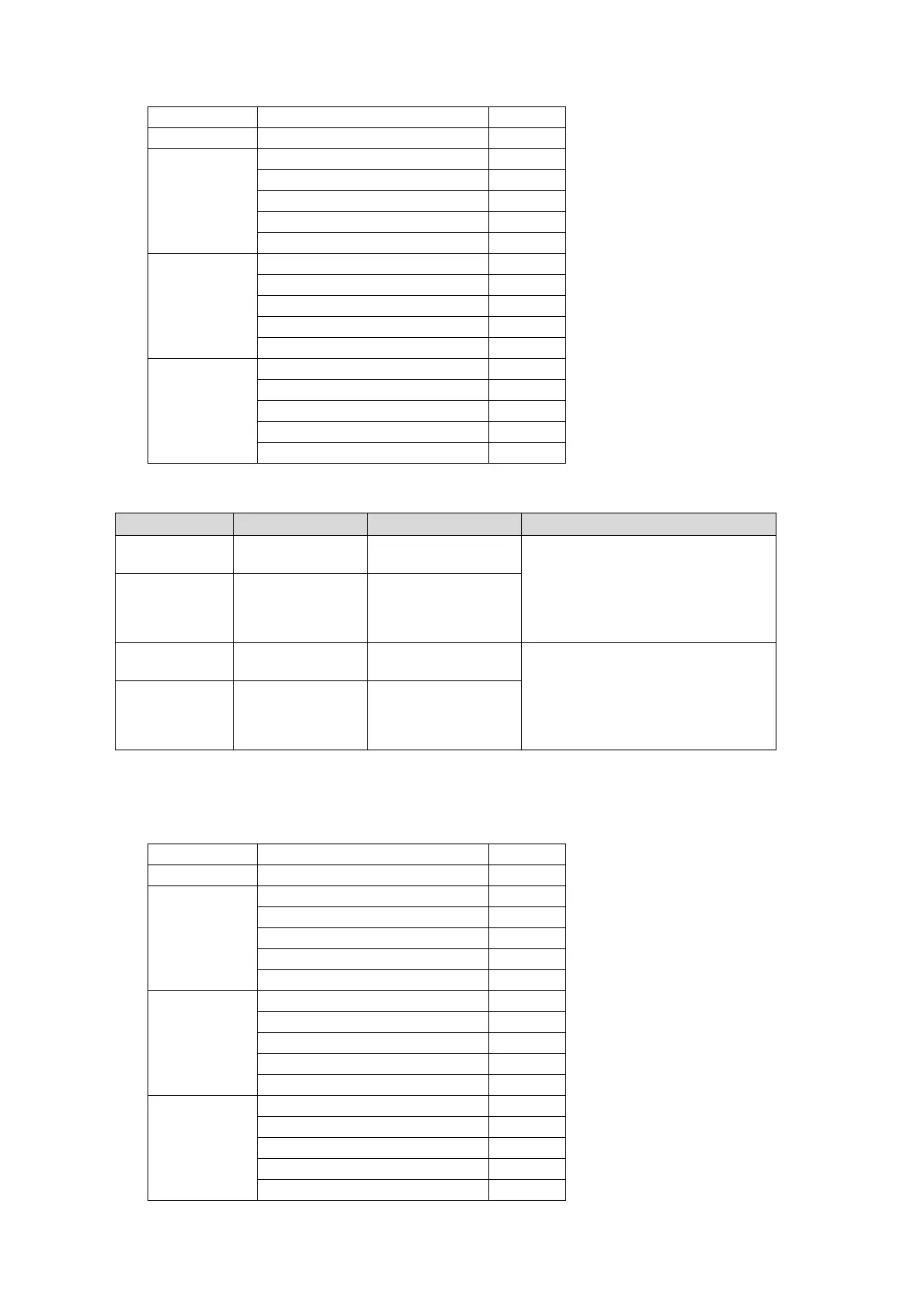
*2 The default value varies depending on the Synchro Mode setting as shown in the below
table. The set value will be reset to its relevant default value whenever the Synchro Mode
setting is changed.
SYNCHRO IN SEL Default
FRAME ─ 0
LINE
SDI1, 2 1
Composite (525/60) 3
Composite (625/50) 4
Component (Y/C) 4
COMPONENT (others) 1
AVDL
SDI1, 2 1
Composite (525/60) 3
Composite (625/50) 4
Component (Y/C) 4
COMPONENT (others) 1
INPUT
SDI1, 2 0
Composite (525/60) 2
Composite (625/50) 3
Component (Y/C) 4
Component (others) 1