GE HEALTHCARE
DIRECTION 2307224-100, REVISION 6DISCOVERY LS SYSTEM SERVICE MANUAL
Chapter 2 - Discovery LS System Safety Information Page 51
Lamps and LEDS
There are a number of lamps/LEDS on the STC chassis backplane (Figure 2-14) that indicate the
functional state of the gantry (Table 2-1).
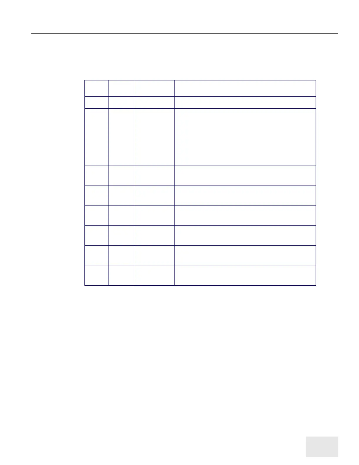
Table 2-1: LED Indication - Functional State of the Gantry
Note: The descriptions in Table 2-1 for DS1 through DS8 apply when its associated LED is illuminated.
LED # Color Label Description
DS1 Green C Pulse C Pulse indicator from Axial Encoder
DS2 Green RST Indicates status of the HVDC and gantry drives
circuit in PDU:
On (Steady) = HVDC and Drives enabled.
Slow Flash = E-Stop activated; HVDC and Drives
disabled.
Fast Flash = Table Tape Switch activated; Cradle,
Tilt and Elevation disabled.
DS3 Yellow AX DR ON Indicates the Axial Drive Contactor in the PDU is
energized.
DS4 Green ENBL Indicates the Axial Drive Contactor in the PDU is
enabled.
DS5 Yellow HVDC ON Indicates the HVDC Contactor in the PDU is
energized.
DS6 Green ENBL Indicates the HVDC Contactor in the PDU is
enabled.
DS7 Yellow 120 VAC ON Indicates the Gantry 120 VAC Contactor in the PDU
is energized.
DS8 Green ENBL Indicates the Gantry 120 VAC Contactor in the PDU
is enabled.