configuration with full power for as long as the router is operational. In the two-PEM
high-line configuration, slots PEM0 and PEM1 or PEM2 and PEM3 are used. The high-line
configuration requires two power supplies, with the third and fourth providing
redundancy. With high-capacity power supplies, you must have a minimum of two
power supplies installed in the router.
Related
Documentation
MX480 Chassis Description on page 9•
• MX480 Power System Description on page 99
• MX480 AC Power Supply LEDs on page 102
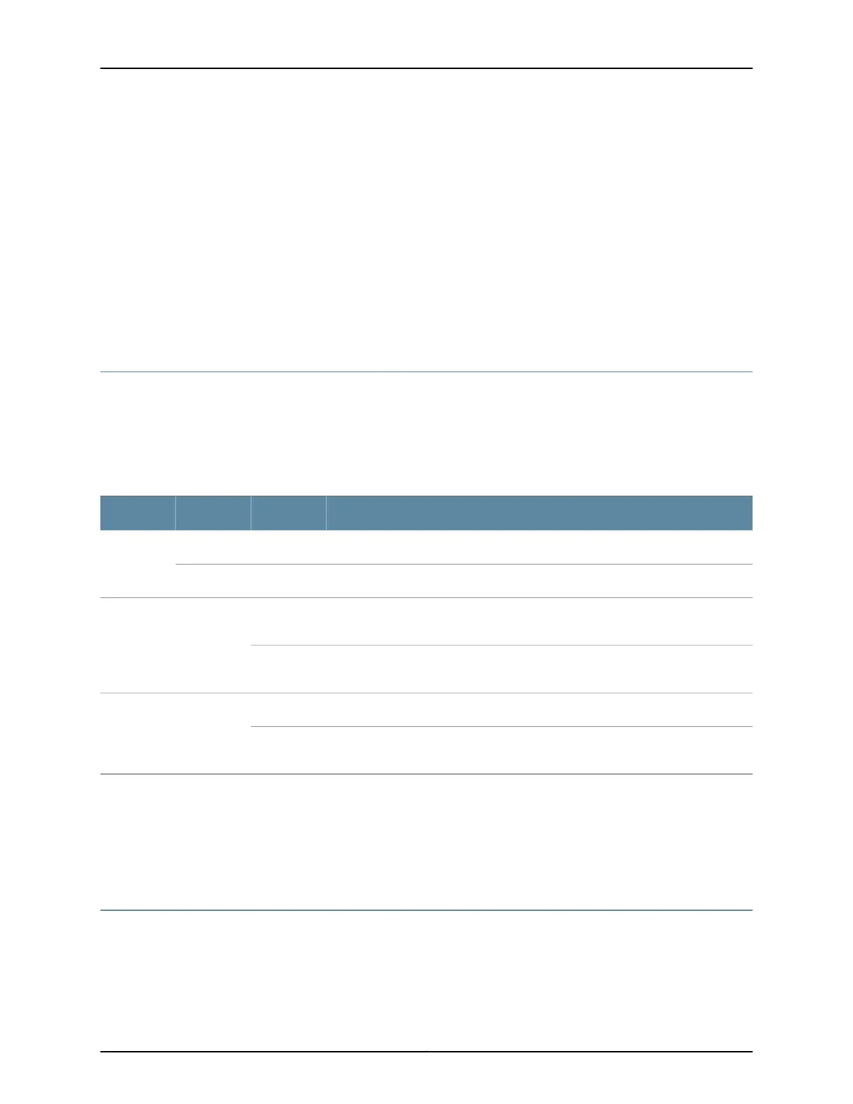
MX480 AC Power Supply LEDs
Each AC power supply faceplate contains three LEDs that indicate the status of the
power supply (see Table 62 on page 102). The power supply status is also reflected in
two LEDs on the craft interface. In addition, a power supply failure triggers the red alarm
LED on the craft interface.
Table 62: AC Power Supply LEDs
DescriptionStateColorLabel
AC power input voltage is below 78 VAC.OffYellowAC OK
AC power input voltage is within 78–264 VAC.OnGreen
DC power outputs generated by the power supply are not within the normal
operating ranges.
OffGreenDC OK
DC power outputs generated by the power supply are within the normal operating
ranges.
On
Power supply is functioning normally.OffRedPS FAIL
Power supply is not functioning normally and its output voltage is out of regulation
limits. Check AC OK and DC OK LEDs for more information.
On
Related
Documentation
MX480 Chassis Description on page 9•
• MX480 Power System Description on page 99
• MX480 AC Power Supply Description on page 100
MX480 DC Power Supply Description
Each DC power supply weighs approximately 3.8 lb (1.7 kg) and consists of one DC input
(–48 VDC and return), one 40 A (–48 VDC) circuit breaker, a fan, and LEDs to monitor
the status of the power supply. Figure 35 on page 103 shows the power supply. Each DC
Copyright © 2017, Juniper Networks, Inc.102
MX480 3D Universal Edge Router Hardware Guide